Circuit explanation of Receiver-1
|
FET amplification circuit is used for a high frequency amplification circuit of the receiver.
It is because the getting of parts is easy. So, it doesn't have high sensitivity. To make the receiver with high sensitivity, the circuit which used IC for FM receiver is good. 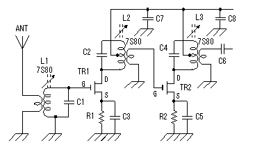 The 2 stages FET amplifier is used for the high frequency amplification. The FET amplifies only at the voltage to apply to gate (G). The resistor to be putting in the source (S) of the FET is to make the bias voltage of the gate. When making a resistance value big, voltage of the source goes up to the grounding and the bias voltage becomes big. In case of the gain of the amplifier is big, when the signal of the output returns to the input, an amplifier oscillates. In the case, it makes this resistance value big and the gain must be lowered. The power of the FET connects with the center tap of the coil (L2 and L3) to be putting in the side of drain (D). This is to make do operation to have been stable, improving the characteristic of the resonance circuit. The characteristic of the resonance circuit is called queue (Q). The ideal resonance circuit picks up only a resonant frequency. However, the actual resonance circuit becomes a shape like the mountain which made a resonant frequency a top. When the Q of the resonance circuit is high, the voltage at the resonant frequency becomes high and the resonant characteristic becomes good. 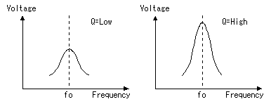  Rectifying the output of the high-frequency amplifier directly with Germanium diode and it makes the DC voltage from high frequency voltage. This circuit can get twice voltage compared with usual rectification circuit. Because the charging takes time when the value of the capacitor (C6) to use for input is big, the change of the output voltage becomes late. I decided a value of this capacitor by the cut & try. 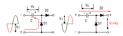 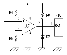 The DC voltage which was made with high frequency detection circuit changes at the strength of the electric wave to receive. The DC voltage which was made with high frequency detection circuit changes at the strength of the electric wave to receive.At the circuit this time, it identifies a control code in the existence in the electric wave. It makes the output of the voltage comparator H level condition if receiving an electric wave and it makes it an L level condition if not receiving. Slightly positive voltage is applied to the negative terminal of IC1 to prevent from a malfunction by the noise. It uses 10 k-ohm for R4, 100 ohm for R5 and the power supply voltage is 12 V. So, the voltage of the negative terminal is 12x100/(10000+100)=0.12 V. Probably, because there is no noise, a negative terminal may ground. When the output voltage (the positive terminal input) of the detection circuit becomes higher than the voltage of the negative terminal, the output of the voltage comparator becomes H level. Because a Zener diode (for 5 V) is connected with the output, the H level is 5 V. This voltage doesn't exceed the permission voltage of PIC.  It puts a vibrator to make do the operation of PIC. A correct oscillation frequency is gotten when there is a crystal oscillator as the vibrator. This time, I used the resonator which used a ceramic. Because to make do the high-speed operation of PIC isn't necessary at the circuit this time, the oscillation frequency is 4 MHz.  RB5 and RB7 port of PIC make do the operation of the relays. It is converting the output voltage of PIC with the transistor. It makes LED light up to find the operation of the relay. It puts a resistor in the LED in series and it is limiting the electric current which flows through the LED to about 10 mA. It is putting a diode in parallel with the relay. When the drive electric current of the relay passes away, the back electromotive force occurs to the coil of the relay. A transistor is prevented from the high voltage by passing the electric current of the back electromotive force to this diode. Because the relay to be using this time is small, there are few gravities that the transistor breaks even if it doesn't put a diode. I put it for the safety. 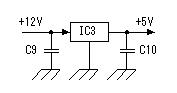 3 terminal regulator is used to make the stable +5V voltage which PIC needs from 12V power. It is enough in the 100mA type because it uses for PIC only. |