Performance test of Ultrasonic Range Meter
|
I confirmed the performance of the Ultrasonic Range Meter. 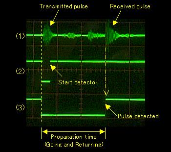 The photograph on the left is the one to have observed the signal when measuring a 2.36m distance. Observation points are shown below. (1) is 1st pin of IC1 ( It is a signal after the amplification with the operational amplifier. ) (2) is 8th pin of IC3 ( It is a detection holding circuit gate signal by PIC. ) (3) is 11th pin of IC3 ( It is an output signal of the detection holding circuit. ) When (2) is an L level, the detector stops. You can find that a malfunction by the transmission pulse is prevented. The prevention time of this circuit is about 1.5 milliseconds. There is possibility to malfunction when short any more. Some feeble reflection signals are received until it detects a reception pulse. Because the threshold voltage of the signal detector of IC2 is working effectively, those feeble signals are not detected. The signal of (3) changes to H level from L level when detecting a reception pulse. This signal is detected by the capture feature of PIC and the propagation time of the ultrasonic is measured.
When wanting to do long-range measurement, it is possible to change software even if it doesn't change hardware of it. In this case, I think that it is better when putting a sound horn to concentrate a ultrasonic.  I confirmed a display in distance measurement of 1 m.
The temperature to display 1.00 is a calculation value. At this equipment, it isn't possible to do an adjustment with detailed calibration value. It is 8 steps. So, it is a reference value. To change a calibration range, the change of the software processing by the value which A/D converted is needed. When doing this confirmation, I found the opposite connection of the calibration resistor. The connection in the center is right but the connection in the both edges is opposite. I intended to turn to the right when the ambient temperature was high. However, the actual operation is opposite. Because it is not in the problem in case of practical use, I don't change it. A schematic and a pattern drawing are corrected. |