Control voltage wave form observation Control voltage wave form observation
In the first program which I made for this equipment, the pulse to control a lamp was to do 9.8KHz (the 102.4 µsec period) being. After controlling a 10-W lamp, I judged that it was working normally. However, as a result of the detailed investigation, I found what needs improvement.
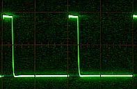
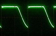
The output wave forms with the 1st program are shown below.
VR=20% |
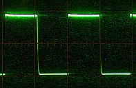
VR=50% |
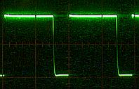
VR=70% |
| In case of VR=80%, the output was always H level. |
You can find the thing that the falling edge isn't sharp. The following phenomenon occurs with this.
| 1. | Because the falling edge of the wave form is gentle, the control of the dark side and the bright side can not be controlled smoothly. |
| 2. | The electricity consumption of the FET increases. |
Some cause that the falling edge becomes gentle can be assumed. I think that the OFF characteristic of the FET is a prime factor. When referring to the data sheet, you can find that the turn-off delay time of 2SJ471 is approximately 10 times the turn-on delay time in case of no-load.
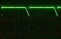
I will show the wave forms of each point at VR=50% below.
 The voltage of the B point is reversed by TR1.
The size of wave from of A point is adjusted to make it easy to watch.
The voltage of the B point is reversed by TR1.
The size of wave from of A point is adjusted to make it easy to watch.
Improvement
Because to change a hardware was troublesome, I improved only by the software. I made the frequency of PWM to 610Hz. It isn't need to control a lamp with near 10KHz.
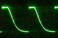
I will show a output wave after improvement below.
The wave form seems to be improved. However, the transition time of falling edge isn't changed. It is because of 16 times of periods that it seems to have been improved.
Because the period of the control pulse became long, the FET electricity consumption was improved.
The change part of the software is the prescaler set value of timer2. I changed it to 1:16.
Before improvement
 | 041
042
043
044 | movlw d'255' ;Period=102.4usec(9.8KHz)
movwf pr2 ;Set PR2 register
bcf status,rp0 ;Change to Bank0
movlw b'00000100' ;Post=1:1 TMR2=ON Pre=1:1 |
After improvement
| 041
042
043
044 | movlw d'255' ;Period=1638.4usec(610Hz)
movwf pr2 ;Set PR2 register
bcf status,rp0 ;Change to Bank0
movlw b'00000110' ;Pst=1:1 TMR2=ON Pre=1:16 |
The set value of timer2 should not be changed. When having changed this value, the output of PWM has always become H level before becoming the maximum (255) of the A/D converter.
I didn't change taking-in period (1mS) with voltage by the variable resistor.
The A/D converted value is set to the CCPR1L register. The value is used in PWM control of the next period. There is no problem even if CCPR1L register is rewritten more than one time before PWM control is done.
 |