Circuit explanation
of Count-down timer
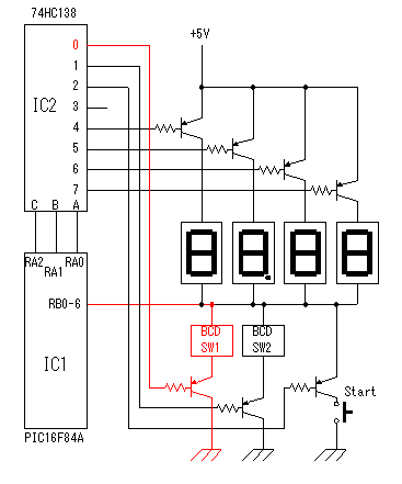 At this circuit, the selection of seven devices are done using the decoder(74HC138).
A device number is specified by RA0,1,2 of PIC. The selection of the device is done by setting the output of the decoder into the PNP-type transistor(2SA1015). The flow of the current through the transistor at the selected device is possible. The transistor of the device which isn't selected is detached from the circuit because it is in the OFF condition. BCD switch (Input), Start switch (Input) and LED (Output) are controlled only by port B. According to the selected device, a mode of port B is changed. 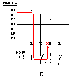 As for the terminal of the BCD switch, the terminals become a short circuit condition each other with the specified figure. The illegal current flow through the BCD switch. The diodes are used to prevent from this. The 7 segment LEDs are connected with port B,too, but the illegal current dosen't flow because LED itself is a diode. When only one BCD-SW is connected with port B, this circuit is unnecessary. However, when more than one BCD-SW and 7 segment LED are connected, it is indispensable. 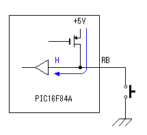 As for the BCD switch, the terminal except the grounded terminal is in the open condition(It is connected with nowhere). The pull-up function of PIC is used to make an open terminal H level surely. The pull-up circuit works when making the RPBI bit of OPTION_REG '0'. The pull-up function works only when the port is an input mode. In the output mode, this circuit doesn't influence. A start switch is made H level by the pull-up function in the off condition of the switch in the same way the BCD switch. The port A which connects a stop switch doesn't have a pull-up function. Therefore, it is pull-uped by the resistor outside. 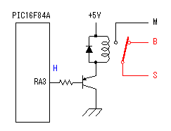 RA3 port is used for the relay control to make do a relay in the continuous control action. The 25-mA can be applied to the port of PIC16F84A. In case of the relay which was used this time, when adding +5 V to the drive coil, the flowing current is about 23-mA. This is near the upper limit. So, I decided to drive a relay using the transistor for the safety. The maximum of 150-mA current can be passed to the collector of the used transistor. 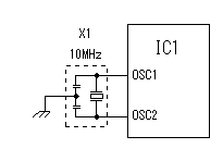 This is the circuit which used 10-MHz resonator. It is very simple. 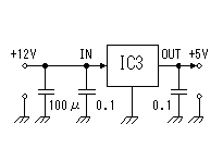 As for the 7 segment LED, only 1 digit lights up at the same time. The whole operating current is as follows approximately.
I used a 100 mA-type regulator. |