
 PIC PIC
This is PIC16F84A. In case of PIC16F84A, it is possible to use a clock frequency upto 20 MHz. The circuit this time, I am using 10-MHz resonator.
4-to-16 line Decoder ( 74HC154 )

This is the IC which decodes the binary code of 4 bits.
16 conditions can be expressed by 4 bits. 74HC154 outputs only one an L level out of 16 by the 4-bit input condition.
The following table shows correspondence of the input and the output of 74HC154.
| Input | Output |
| D | C | B | A | 00 | 01 | 02 | 03 | 04 | 05 | 06 | 07 | 08 | 09 | 10 | 11 | 12 | 13 | 14 | 15 |
| L | L | L | L | L | H | H | H | H | H | H | H | H | H | H | H | H | H | H | H |
| L | L | L | H | H | L | H | H | H | H | H | H | H | H | H | H | H | H | H | H |
| L | L | H | L | H | H | L | H | H | H | H | H | H | H | H | H | H | H | H | H |
| L | L | H | H | H | H | H | L | H | H | H | H | H | H | H | H | H | H | H | H |
| L | H | L | L | H | H | H | H | L | H | H | H | H | H | H | H | H | H | H | H |
| L | H | L | H | H | H | H | H | H | L | H | H | H | H | H | H | H | H | H | H |
| L | H | H | L | H | H | H | H | H | H | L | H | H | H | H | H | H | H | H | H |
| L | H | H | H | H | H | H | H | H | H | H | L | H | H | H | H | H | H | H | H |
| H | L | L | L | H | H | H | H | H | H | H | H | L | H | H | H | H | H | H | H |
| H | L | L | H | H | H | H | H | H | H | H | H | H | L | H | H | H | H | H | H |
| H | L | H | L | H | H | H | H | H | H | H | H | H | H | L | H | H | H | H | H |
| H | L | H | H | H | H | H | H | H | H | H | H | H | H | H | L | H | H | H | H |
| H | H | L | L | H | H | H | H | H | H | H | H | H | H | H | H | L | H | H | H |
| H | H | L | H | H | H | H | H | H | H | H | H | H | H | H | H | H | L | H | H |
| H | H | H | L | H | H | H | H | H | H | H | H | H | H | H | H | H | H | L | H |
| H | H | H | H | H | H | H | H | H | H | H | H | H | H | H | H | H | H | H | L |
|
3 terminal regulator ( 7805 )
This regulator is used to make the stable +5 voltage.
At the circuit this time, the maximum number that the LED lights up at the same time is 8. So, the maximum of the power current is about 100 mA. 100 mA-type 78L05 can be used. But, it is barely.
I used a 1-A type for the safety.
LED control transistor
This transistor is used to control the lighting-up row of the LED. I used PNP type.
IC socket
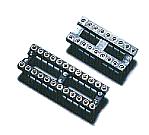
The PIC is mounted after writing a program by programmer. So, the IC socket is needed.
I used a socket for the mounting of 74HC154, too. 74HC154 is the IC of 24 pins but the width is the same as the IC of 14 pins. This type is called a slim type.(Only in Japan?)
Resonator
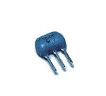
I used 10-MHz resonator. A ceramic vibrator and capacitors for the oscillation are combined inside.
LED
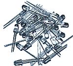
I used high brightness-type LEDs with 5-mm diameter.
Because it was 1/16 in the lighting-up time by PIC, I used an high brightness type.
Resistor network
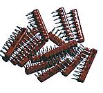
Resistor networks are used for current control (330-ohm) of the LED.
As for the resistor network, more than one resistor was modularized to one.
The resistor network which I used this time is the type that eight resistors are housed in one module.
One side of the resistors are connected inside. So, they have nine lead wires. There are one common lead wire and eight lead wires of each resistor.
Resistor
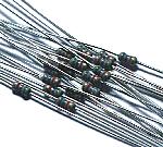
These resistors(5.6K ohm) are used to limit the base current of the transistor.
It is enough in the one of 1/8 W.
Electrolytic capacitor
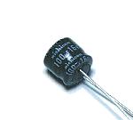
This capacitor is used to be stabilized of the input voltage and to bypass low frequency noise.
Multilayer ceramic capacitor
These capacitors are used to bypass the high frequency noise of the input and output of the power supply.
Printed board
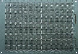
This is an universal printed board with 40 x 55 halls.
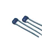
Wiring terminal
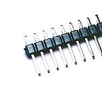
This terminal is used to connect a power supply wire.
Stud
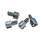
This is used as the leg of the printed board.
Stud
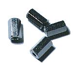
This stud is used to put an acrylic board in the front.
I used one with 10-mm length.
|