Circuit explanation of LED flasher
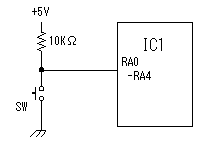
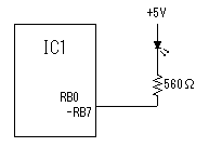
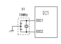
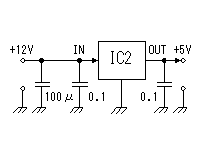
 Five pins from RA0 to RA4 are used as the input pin. These pins are pull-uped with 10K ohm resisters. So, when a switch isn't pushed, the input becomes H level ( +5V ). and when a switch is pushed, it will become L level ( 0V ). When the switch closes, the chattering occurs. The chattering is the phenomenon which occurs with the bound of the point of contact. The opening and shutting of a point of contact is repeated in short time.. I don't put the prevention circuit of the chattering at the circuit this time. When the software detects that the switch is closed once, the blink processing of LEDs are executed in the time which is longer than the chattering.  Eight pins from RB0 to RB7 are used for the output pin. The anode side of the LED is connected with +5 V and the cathode side is controlled by PIC via the resistor. So, when the output of PIC is H level (+5V), the LED goes out and when the output of PIC is L level (0V), the LED lights up. I am using high brightness type LED to make an current flow little.  This is the circuit which used 10-MHz resonator. It is very simple.  3 terminal regulator is used to get +5V output from +12V power in. Because it is suppressing the current of the LED, a 100 mA-type regulator is enough. |