|
As for the MPLAB tool of the Microchip Inc., a frequently new version is released.
The operation methods differ in Ver5 and Ver6 of MPLAB.
I will introduce about the basic usage of MPLAB Ver6.50 here.
A function difference between Ver5 and Ver6 isn't explained.
 The premise of explanation The premise of explanation |  Starting MPLAB Starting MPLAB |

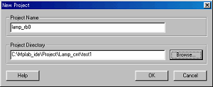
I use the software for the synchronization pulse detection which was used with "Decorative light Controller" as an example.
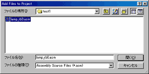
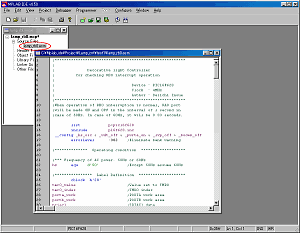
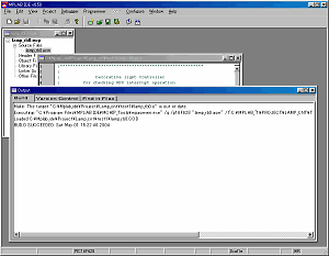
A source file is the premise stored in test1 folder as shown in the above figure. |
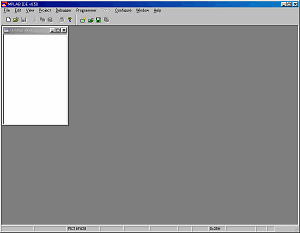
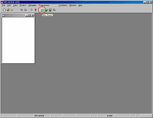
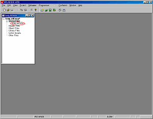
When starting MPLAB, a screen like the figure above is displayed. |
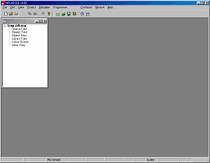
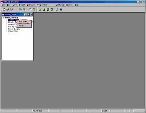
 Setup of a project Setup of a project |
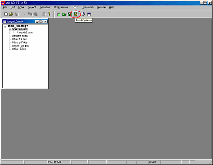
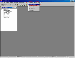
Click Build Options icon and set the condition of the project. |
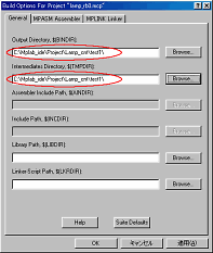
Set Output Directory and Intermediates Directory in the General tab.
I did to the place which is the same as the source file. |
|
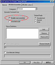
Next, click MPASM Assembler tab and have Disable case sensitivity checking mark.
My source code is written by the lowercase but the INC file of the standard label definition is written by the uppercase. This setting makes a case sensitivity invalid.
When assembling my source file, this setting is indispensable. |
 Displaying of a Listing file Displaying of a Listing file |
| The quantity consumed of the program memory is displayed in the Listing file. |
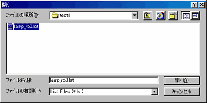
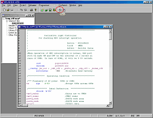
Click Open File icon, choose * .lst by the file type and open the Listing file. |
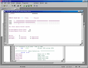
The state of memory is displayed on the last of the Listing file.
This time, it is displayed as follows.
Program Memory Words Used: 91
Program Memory Words Free: 1957 |
 Setting of a debugger Setting of a debugger |
| The debugger is convenient for the operation confirmation of the assembled program. |
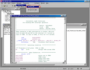
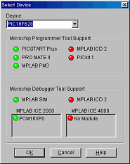
The simulator of MPLAB can be used when choosing Debugger -> Select Tool -> MPLAB SIM by the menu bar. |
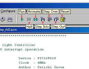
An icon for the debugging is added to the icon bar.
| Run | Execute program code until a breakpoint is encountered or until Halt is selected. |
| Halt | Halt (stop) the execution of program code. |
| Animate | Continually Step Into instructions. |
| Step Into | Execute the current instruction and then halt. |
| Step Over |
Execute the instruction at the current program counter location, then halt. If the instruction is a call instruction, execute the called subroutine and halt at the address following the call.
It is convenient when to check the processing step of the subroutine isn't necessary. |
| Step Out | In case of subroutine, step out of current location in a function and return to main program. |
| Reset | Reset as specified. |
|
 |


