 Design Rule Check Design Rule Check
Before creating a pattern, the design condition should be set to DRC(Design Rule Check). A general default value is already set on the DRC but I recommend to confirm the main item.

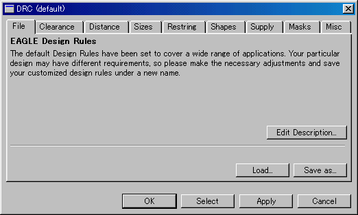
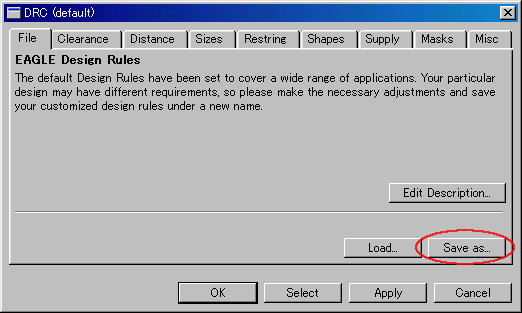
When pushing a DRC icon, following dialog is displayed.
At first, DRC(default) which an eagle default value is set is displayed.
 Clearance Clearance
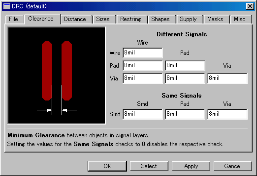
The interval of Wire, Pad and Via is designated by the Clearance tag. The value which is displayed in Different Signals is a clearance value. The default is 8mil. Because 1 inch is 25.4mm and 1mil is 1/1000 inches, so 8mil is about 0.2mm. This value means that the minimum wiring interval is 8mil. It is not the fact that all wiring is wired in the 8mil interval. When doing a printed board in hand-made, I think that it had better set to a little big value. Like 16mil.
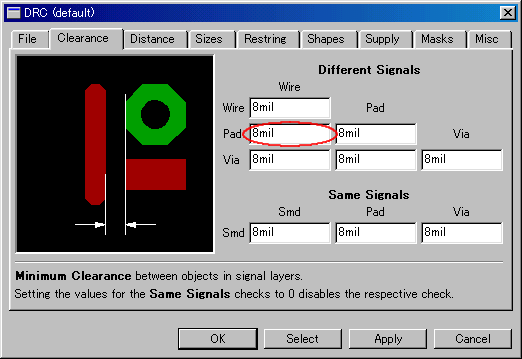 The figure above is when choosing an item between Wire and Pad.
You can recognize a setting part with the figure.
 Distance Distance
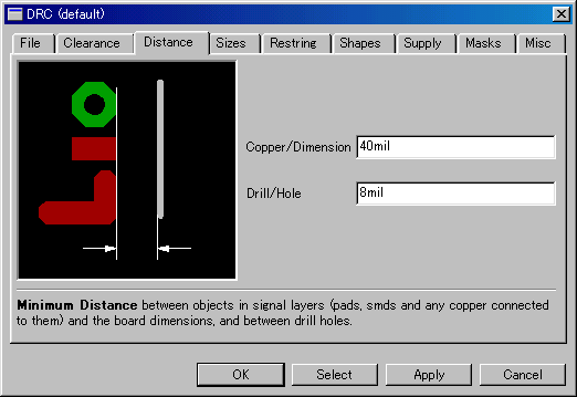
By the Distance tag, the minimum value of the interval of the edge of the printed board and the wiring pattern, the interval among the drill holes and so on is designated. 40mil is about 1mm.
 Sizes Sizes
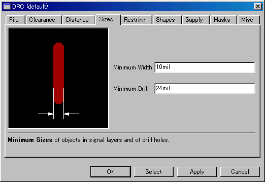
By the Sizes tag, the minimum width of the wiring pattern and the minimum size of the drill holes are designated. 10mil is about 0.25mm.
When wiring using Net classes on the schematic, the value which is set here is used for the value of the Default class.
 Restring Restring
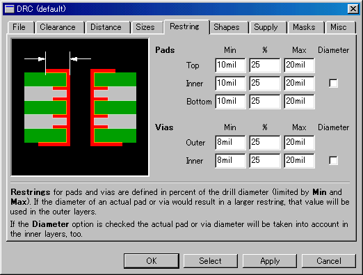
Restring is the size of the part except the hole of the pad for the component mounting. In case of component mounting, it is the size of the soldering part.
When the size of the pad which is specified by the library and so on is bigger than the value to set in Restring, the value to set in Restring isn't applied. When the size which is specified by the library and so on is smaller than the value to set in Restring, the value to set in Restring is applied. So, Restring designates a minimum value with the size of the pad.
The relation of Min, % and Max is as follows. It isn't possible to make Min to be the value which is bigger than Max.
 | Ex. ( Assume Drill : 32mil, Diameter : 64mil. In this case the Restring value is (64-32)/2=16mil. ) |
 |
When Min=20mil, %=300, Max=20mil, Restring value becomes 20mil.
Even if the value by the % is big, it doesn't become above 20mil which is Max value. |
 |
When Min=1mil, %=70, Max=200mil, Restring value becomes 22.4mil. Drill(32mil) x 0.7=22.4mil.
Even if the Min value is small, because the value by the % is bigger, the value by the % is used. |
 |
When Min=20mil, %=0, Max=200mil, Restring value becomes 20mil.
Even if the % is 0, because the value of the Min is bigger, the value of Min is used. |
The Inner is the designation for the multi-layer printed board. In case of the printed board with single layer or double layers, it is not effective.
 Other designations ( Shapes, Supply, Masks, Misc ) Other designations ( Shapes, Supply, Masks, Misc )
As the setting item except the above, there are Shapes, Supply, Masks and Misc. I think there is no problem if it's used as the default value. Use by the setting for which you are necessary.
 | Shapes : | This is the setting about the form of the pad corner for the component mounting. |
| Supply : | This is the setting about the pad for the power supply. |
| Masks : | This is the setting about the solder resist mask for the automatic soldering. |
| Misc : | This is the setting about the DRC requirements. |
 Save of the setting ( File ) Save of the setting ( File )
The changing contents of the DRC can be used for the other project by saving them in the file. The extension of the file is "dru". Usually, this file is saved into the "dru" folder under EAGLE folder. You can change a save folder.
The Load button is used to read a saved file.
 |
