The turning-over period of the inverter is decided by capacitor(C), resistance(R) and threshold voltage(VT). Strictly, it changes more with the discharge situation of C, too. In case of inverter A, Cx and Rx are related and in case of inverter B, Cy and Ry are related. |
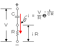
The electric current change when voltage (V) is applied to the circuit which capacitor (C) and resistor (R) were connected with in series can be calculated by the following formula. |

 |  | i | : | Electric current which changes in the time (A) |
| V | : | Applied voltage (V) |
| R | : | Resistance value (ohm) |
| e | : |
Base of the natural logarithm
(2.71828) |
| t | : | Elapsed time after the charging beginning (sec) |
| CR | : | Capacitive time constant (C x R) |
The change of the voltage which is applied to the both edges of the resistor (R) becomes the following formula.
The time that this value becomes equal to the VT becomes the reversing time of the inverter.
In the reversing time (t), it becomes the following formula.
This value is time with half period.
It attempts to adapt the actual value. The value of the logarithm see the logarithm table.
Condition
 | C = 47µF |  | R = 12k-ohm |  | VT = 1.4V |  | V = 4.5V |
 | t | = | - ( 47 * 10-6 ) * ( 12 * 103 ) * ln ( 1.4 / 4.5 ) |
| = | - ( 564 * 10-3 ) * ln ( 0.31 ) |
| = | - ( 564 * 10-3 ) * ( -1.17 ) |
| = | 660 * 10-3 |
| = | 0,66 sec |
With the time (TH) of the high level condition and the time (TL) of the low level condition supposing that it is the same, the frequency is as follows.
 | f | = | 1 / ( TH + TL ) = 1 / ( 0.66 + 0.66 ) |
| = | 0.76 Hz |
Because the threshold voltage (VT) depends on the IC little, it is sometimes different from the calculation result. When the value of the combination of C6 and R1, and the value of the combination of C5 and R2 are different, the time (TH) of the high level condition and the time (TL) of the low level condition are different. The condition with the time of the high level and the same time of the low level is called 50% of the duties.
It was to 0.93 Hz be when measuring the frequency
of the circuit which was made this time.
The main cause when the period doesn't suit the computation result includes the following.
 Discharging of the capacitor Discharging of the capacitor
When to discharge of the capacitor isn't done, the time which reaches the threshold voltage becomes short.
 High level voltage(V) High level voltage(V)
The high level voltage of the inverter output influences.
The circuit this time is passing the electric current which is bigger than the rating because of the transistor drive. In the measurement, it becomes about 4.5 V. When this voltage becomes low, the period becomes short.
 Threshold voltage(VT) Threshold voltage(VT)
It depends on the kind of the IC. The lower this voltage is, the longer the period becomes.
 Voltage drop of the diode Voltage drop of the diode
The voltage drop of the diode influences. With the electric current which flows through the diode, the voltage drop occurs with the diode. The bigger this value is, the shorter the period becomes.
|
|

