
 Timer IC ( 555 ) Timer IC ( 555 )
This is the IC which is often used as the IC for the timer.
The wide range timer value can be gotten by the capacitor and the resistor outside.
Resistor
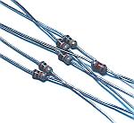
As the resistor, I am using the type that the permission electric power is 1/8 W. More than 1/8-W resistor can be used, too.
Electrolytic capacitor
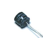
This is the capacitor to decide a timer value. At the circuit this time, a 100-µF electrolytic capacitor is used to make a timer value in a maximum of about 2 minutes.
IC socket
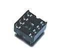
The IC can be put to direct to the printed board, too. This time, a socket is used.
Variable resistor
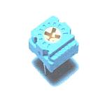
This is a small variable resistor to adjust a timer value. At the circuit this time, it is possible to set time from about 10 seconds to 120 seconds with this resistor.
Baton switch
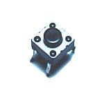
This is the start switch of the timer. This is a non lock-type switch and the point of contact closes only when pushing a switch.
Transistor for the relay drive ( 2SC1815 )
The 555 timer IC can pass an output current in a maximum of 200mA. So, even if it drives a relay directly with 555 IC, there is no problem. I used a transistor for the relay drive to reduce the load of 555 IC. I have the experience of the abnormally operation when driving a relay directly by the IC. It is not 555. Since then, when driving a relay, I am using a transistor. Even if you don't use a transistor, there is no problem. In the case, a relay is put between output of 555 IC and grounding.
Output relay ( G5V-1 )
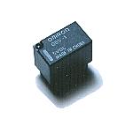
This relay operates in operation of the timer and can control a circuit outside.
This is the small relay which is made by the OMRON Inc..
 |
| Drive voltage | DC 12V |
| Number of contacts | 1 |
| Contact capacity | 30VDC | 1.0A |
| 125VAC | 0.5A |
| 80VDC | 0.3A |
|
Overvoltage protection diode ( 1S1588 )
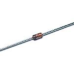
This is the diode to protect a transistor from the reverse voltage which occurs when cutting the drive electric current of the relay. The high voltage which applies over the transistor is prevented by floating the electric current which occurs in the reverse voltage to the diode.
Light Emitting Diode
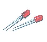
It lights up in operation of the timer and the timer operation can be confirmed.
Printed board
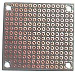
I cut an universal printed board according to the space of the circuit.
Stud
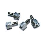
I used studs as the leg of the printed board. The plastic spacer can be used, too.
It is to prevent printed board wiring side's touching the metal which was put below.
Wiring terminal
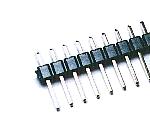
This is the terminal to connect a power line and an output line. It is possible to wire directly to the printed board without this terminal.
|