 Block diagram Block diagram
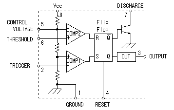
NE555 is composed of the voltage comparators, the flip-flop and the transistor for the discharge. The composition is simple, but it is excellent one.
Three resistors are connected with the inside in series and the power supply voltage(Vcc) is divided in 3. This composition is an excellent point. 1/3 with power supply voltage is applied to the positive input terminal of the comparator (COMP1) and the voltage of 2/3 is applied to the negative terminal of the comparator (COMP2). When the voltage of the trigger terminal(TRIGGER) is less than 1/3 of the power supply voltage, the S terminal of the flip-flop(FF) becomes H level and an FF is set. When the voltage of the threshold terminal(THRESHOLD) is more than 2/3 of the power supply voltage, the R terminal of the FF becomes H level and an FF is reset.
 The oscillation operation explanation The oscillation operation explanation
I will explain the circuit operation below.
 The condition immediately after the turning on The condition immediately after the turning on
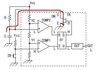
 The condition when turning on the power becomes the condition which is shown in the figure on the left. The L is 0 V almost, showing the low level. H is the value which is high level and is near Vcc. The flip-flop (FF) is the SR type. The Q becomes H and The condition when turning on the power becomes the condition which is shown in the figure on the left. The L is 0 V almost, showing the low level. H is the value which is high level and is near Vcc. The flip-flop (FF) is the SR type. The Q becomes H and  becomes the L when S becomes H. After that, even if S becomes the L, the Q maintains H and becomes the L when S becomes H. After that, even if S becomes the L, the Q maintains H and  maintains the condition of the L. When R becomes H, maintains the condition of the L. When R becomes H,  becomes H and the Q becomes the L. That is, the Q becomes H when a few S become H(the set) and the Q becomes the L when a few R become H(the reset). When S and R become H at the same time, the condition of the Q and becomes H and the Q becomes the L. That is, the Q becomes H when a few S become H(the set) and the Q becomes the L when a few R become H(the reset). When S and R become H at the same time, the condition of the Q and  is unsettled. (I think that both become H). Because is unsettled. (I think that both become H). Because  is H in this condition, TR is in the ON condition and the collector (C) of TR is in the L condition. Therefore, the electric charge doesn't store up in capacitor(C), the (+) terminal with the voltage comparator(COMP2) doesn't cross V2. Because it is, the output of COMP2 is as the L and the FF doesn't become the reset condition. OUT is as the L condition. is H in this condition, TR is in the ON condition and the collector (C) of TR is in the L condition. Therefore, the electric charge doesn't store up in capacitor(C), the (+) terminal with the voltage comparator(COMP2) doesn't cross V2. Because it is, the output of COMP2 is as the L and the FF doesn't become the reset condition. OUT is as the L condition.
 The timer start condition The timer start condition
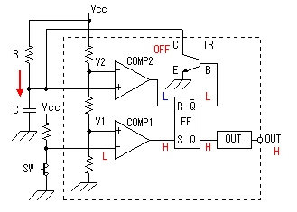
 When the start switch (SW) is pushed, the COMP1 (-) terminal becomes the L condition. When the start switch (SW) is pushed, the COMP1 (-) terminal becomes the L condition.
Because the voltage of the COMP1 (-) terminal became equal to or less than V1 of the (+) terminal, the output of COMP1 becomes the H condition.
With this, the FF becomes the set condition, the Q changes into H,  changes into the L condition and OUT becomes the H condition. changes into the L condition and OUT becomes the H condition.
Because  became the L condition, TR becomes the OFF condition. When TR becomes the OFF condition, the electric charge begins to store up in capacitor(C) through the resistor (R). As the electric charge stores up in capacitor(C), voltage of the both edges of capacitor(C) begins to go up. The start switch (SW) uses the non lock type which turns back after pushing once. In case of being as the pushed condition, OUT doesn't become the L condition even if the timer does in the time-out. When the start switch (SW) turns back, the COMP1 (-) terminal becomes the H condition and to become equal to or more than V1 of the (+) terminal, the output of COMP1 becomes the L condition. The output of COMP1 becomes the L condition and the S terminal of the FF becomes the L condition, the condition of Q and became the L condition, TR becomes the OFF condition. When TR becomes the OFF condition, the electric charge begins to store up in capacitor(C) through the resistor (R). As the electric charge stores up in capacitor(C), voltage of the both edges of capacitor(C) begins to go up. The start switch (SW) uses the non lock type which turns back after pushing once. In case of being as the pushed condition, OUT doesn't become the L condition even if the timer does in the time-out. When the start switch (SW) turns back, the COMP1 (-) terminal becomes the H condition and to become equal to or more than V1 of the (+) terminal, the output of COMP1 becomes the L condition. The output of COMP1 becomes the L condition and the S terminal of the FF becomes the L condition, the condition of Q and  of the FF don't change. While the voltage of capacitor(C) doesn't exceed the voltage V2(the voltage of the COMP2 (-) terminal), FF maintains this condition. of the FF don't change. While the voltage of capacitor(C) doesn't exceed the voltage V2(the voltage of the COMP2 (-) terminal), FF maintains this condition.
 The time-out condition The time-out condition
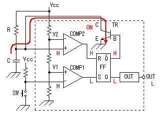
 The output of COMP2 becomes the H condition when the electric charge stores up in capacitor(C) and the voltage of the COMP2 (+) terminal crosses V2 of the (-) terminal. The reset terminal (R) of the FF becomes the H condition with this, the Q becomes the L and The output of COMP2 becomes the H condition when the electric charge stores up in capacitor(C) and the voltage of the COMP2 (+) terminal crosses V2 of the (-) terminal. The reset terminal (R) of the FF becomes the H condition with this, the Q becomes the L and  becomes the H condition. OUT becomes the L condition. becomes the H condition. OUT becomes the L condition.
Because  becomes the H condition, TR becomes the ON condition. Because TR becomes the ON condition, the COMP2 (+) terminal becomes the L condition and the output of COMP2 returns to the L condition. So, the condition of the Q and becomes the H condition, TR becomes the ON condition. Because TR becomes the ON condition, the COMP2 (+) terminal becomes the L condition and the output of COMP2 returns to the L condition. So, the condition of the Q and  don't change, OUT is as the L condition. Also, because TR becomes the ON condition, discharge through TR by the electric charge of capacitor(C) and the electric charge of capacitor(C) passes away. don't change, OUT is as the L condition. Also, because TR becomes the ON condition, discharge through TR by the electric charge of capacitor(C) and the electric charge of capacitor(C) passes away.
By above operation, it returned to the condition before pushing the start switch.
 |

 The condition when turning on the power becomes the condition which is shown in the figure on the left. The L is 0 V almost, showing the low level. H is the value which is high level and is near Vcc. The flip-flop (FF) is the SR type. The Q becomes H and
  When the start switch (SW) is pushed, the COMP1 (-) terminal becomes the L condition.
 The output of COMP2 becomes the H condition when the electric charge stores up in capacitor(C) and the voltage of the COMP2 (+) terminal crosses V2 of the (-) terminal. The reset terminal (R) of the FF becomes the H condition with this, the Q becomes the L and