
 Inverter IC for oscillator ( 4069UB ) Inverter IC for oscillator ( 4069UB )
This logic inverter is used to make about 40Hz to 70Hz square wave.
Regulator IC for the voltage creating of +5V ( 78L05 )
This IC is used to make stable +5V from +12V.
IC socket
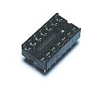
This socket is used to mount 4069UB. It is OK even if IC is mounted directly on the printed board.
Transistor for FET drive ( 2SC1815 )
This is the transistor to drive the MOS FET with the square wave signal by 4069UB. The output of oscillator is converted into the 0V to 12V to control the FET with this transistor.
Variable resistor for the frequency adjustment
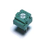
This is the variable resistor to adjust an oscillation frequency.
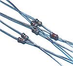
Capacitor for oscillator
I used the tantalum capacitor with 2.2 uF. The electrolytic capacitor is OK.
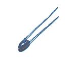
Rresistor
I used the carbon film type of 1/8 W.
Multilayer ceramic capacitor for power bypass

This capacitor is used to pour the high frequency component of the power into the ground.
Electrolytic capacitor for power bypass
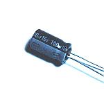
This capacitor is used to pour the low frequency component of the power into the ground.
The capacitor with few ESR(Equivalent Series Resistance) should be used.
Terminal for wiring
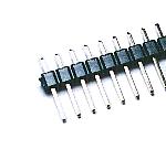
This terminal is used to connect a power line, an FET drive line.
Printed board
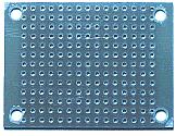
I used an universal printed board for the needed size, cutting.
Stud
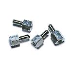
This spacer is used to install the printed board in the case.
Transformer
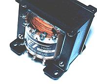
I used the transformer with the following specification.
Primary side voltage : 100V and 110V
Secondary side voltage : 12V (without center-tap)
Secondary side current : 10A
Size : 100mm(W), 90mm(H) and 100mm(D)
Weight : about 2.5Kg
Power MOS FET ( 2SJ471 )
This is P channel MOS FET.
The maximum drain current is 30A.
When the FET is in the ON condition, the resistance between drain and source is 25 milli-ohm. So, the electric power loss when the 10-A electric current flows in the ON condition is 2.5 W.
Power MOS FET ( 2SK2956 )
This is N channel MOS FET.
The maximum drain current is 50A.
When the FET is in the ON condition, the resistance between drain and source is 7 milli-ohm. So, the electric power loss when the 10-A electric current flows in the ON condition is 0.7 W.
Heat sink
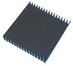
An FET is used in the ON condition or the OFF condition. The electricity consumption of the FET is small. But I used a little large heat sink for the safety.
The size is 100mm x 100mm x 17mm.
Fuse

Fuse must be put to protect when the excessive input current flows.
When the oscillator stops, the switching of the input current stops and the big electric current flows on the secondary side of transformer.
I used a pipe glass-type fuse for the easiness of the exchange.
I used 15A.
Case
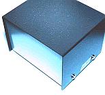
I selected a case according to the size of the transformer.
The size is 150-mm width, 100-mm height and 130-mm depth.
Plug for DC input
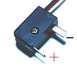
Because there is polarity in the DC input, I am using the plug which has the structure which doesn't connect oppositely.
Outlet for AC output
I used an outlet for the home electronics equipment for AC output.
Wiring material
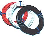
I used wiring materials for 15 A for the wiring which the big electric current of 12 V flows through.
Handle

I put a handle to the top of the case to carry.
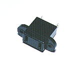
Fixation terminal

This terminal is used to fix the wire of DC 12V.
Wire protector
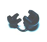
This part is used to protect so as not for input wiring material cover to be damaged.
Terminal cover

This is a cover for the part which soldered wiring material.
Cord binder

When not using the equipment, the input wire can be fixed with this tape.
|