Parts explanation
of the LCD thermometer
|
Most of the parts are contained in the kit.  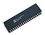 The ICL7136 is the IC for the analog/digital converter. This is the IC to display the analog voltage in the digital. The IC to be using this time is the DIP of the 40 pins. The voltage to ±200mV or ±2V can be measured in few errors.  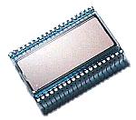 This is the TN(Twisted Nematic)-type liquid crystal display. It is possible to 4 digits display but the display of the maximum figure is only "1". It isn't possible to work continuously in the direct current. However, when applying the about 5-V DC voltage between the backplane (common) and the terminal, the color of the segment which corresponds can be temporarily changed to the black. With this, the correspondence of the terminal and the display segment can be confirmed. When using the 5-V power supply, the resistor as much as 10K-ohm must be put in series to prevent from big electric current's flowing in case of the short circuit. The specification of SP521PR to be using this time is as follows. 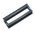 This socket is used to install ICL7136 and the liquid crystal display. It is the socket for the DIP of the 40 pins. The socket to use for the liquid crystal display cuts off either side to make the interval of the pin line wide. In case of the socket for ICL7136, the parts are installed inside the socket. So, when there are the supports in the socket, they must be removed. 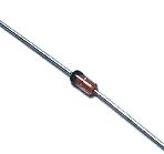 This is the diode to use as the temperature sensor. The original use of this diode is the diode for the switching. The one of the other name can use for the temperature sensor if being the silicon diode. But, the mold type doesn't suit because it is difficult for the temperature change to spread through the joint immediately. The transistor can be used instead of the diode. It connects the base with the collector and it uses the part of the connection between the base and the emitter for the temperature sensor. The use example is mentioned to the manual of ICL7136. When using the transistor for the temperature sensor, the type which is stored in the metallic case suits. The lead wires of the diode are insulated with the tubes that the heat can be endured(the glass fiber tube so on). And, the shielded wire is used for the connection with the thermometer. 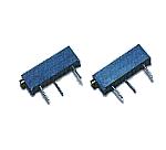 These potentiometers are used for the zero adjustment and the scale adjustment. Because it changes the resistance value by the pitch of the screw, the resistance value can be changed in detail. 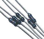 As for the resistors which are contained in the kit, the resistors of 1% of the tolerance are used. As the thermometer, the accuracy with the resistance value isn't too necessary. However, because it handles the minute voltage, there is possibility that the resistance value change by the temperature has an influence on the measurement error. 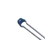 This capacitor is used for the high frequency bypass of the power supply. Because it is for the high frequency bypass, the multilayer ceramic capacitor with the good high frequency characteristic is used. 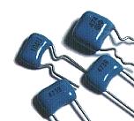 These capacitors are the capacitors which are used for the input voltage measurement, the reference voltage setting and so on of the ICL7136. The polyester film capacitors are used. Because it influences the precision of the measurement, it is better to use the capacitor which few changes of the capacity by the temperature. Also, it is better to use the small size one because the place to install is narrow. 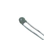 This capacitor is used for the clock generator of ICL7136. To make oscillate at the frequency of about 50 KHz, the ceramic capacitor with the good high frequency characteristic is used. 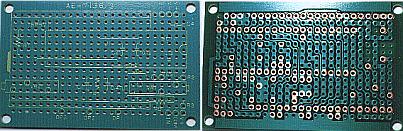 This is the printed board which is attached to the kit. Because the print pattern is already made, you solder the parts only to the fixed position and can make the thermometer. When using the diode sensor, the resistor (R4) to control the electric current of the diode is necessary. As for the pattern of the printed board, the mounting of this resistor isn't considered. The solder resist (the green paint) is painted the mounting position of R4 which is mentioned to the pattern drawing. The solder resist in the part must be scraped off with the cutter knife and so on before mounting the resistor. 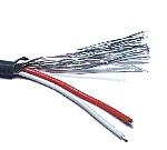 This wire is used to connect the diode temperature sensor and the thermometer. The input impedance of ICL7136 is very high and is easily influenced by the noise signal from outside. So, it makes the influence little by the shielded wire I used the shielded wire of the 2 wires which were at hand, but it is OK in the shielded wire of the single wire. This part isn't contained in the kit. 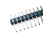 This terminal is used to connect the wire of the temperature sensor and the power supply. This part isn't contained in the kit. 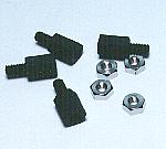 The pattern of the printed board is pictured near the hole for the fixation. There is a gravity which touches the circuit when using the metallic stud. Therefore, I used mold-type stud. Instead of stud, the plastic spacer can be used. Also, the insulation-type washer can be used, too. This part isn't contained in the kit. |