Parts explanation
of the electric power controller
 This is the bidirectional triode thyristor(TRIAC) which I am using this time. It is made by THOABO, but I don't know the detailed data.
RMS On-State Current(IT(RMS))
As for TB12B6C, the heatsink installation part is insulated by the mold. Because it is, the insulation sheet is unnecessary. When the heatsink installation part uses the type which isn't insulated, you use the insulation sheet(Silicon rubber) according to the necessity. The main electricity characteristic of the bidirectional triode thyristor
 I used the heatsink which I had. 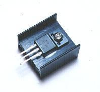 The following is written as the reference with the heatsink size at the manual which is attached to the "Light dimmer kit using TRIAC" of the Akizuki Denshi Tsusho.
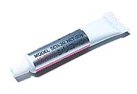 The silicon grease is put in the thermal conductivity to improve theheat conduction between the triac and the heatsink. The silicon grease is the compounding of the white grease. The metallic oxide is mixed in it to improve the thermal conductivity. The silicon grease is painted to the back of the triac. You don't need to paint a lot of it. There is not an effect in the part which was stuck out of the triac. 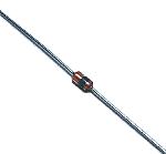 This time, the trigger diode which I am using is N413 which is made by NEC. The breakover voltage (VBO) of N413 is up to 40 V from a minimum of 26 V according to the data sheet. Because there is not polarity, it is OK even if you install in any direction. 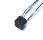 I used the diode bridge for the diode of the hysteresis prevention circuit. I used the one of the maximum voltage of 200 V, and the maximum forward direction electric currents of 1.5 A. As for the flowing electric current, because it is little, the one with the smaller capacity is OK. It is necessary to be careful so as not to make a mistake in the connection of the pole. The four diodes can be used instead of the diode bridge, too.  This is the variable resistor which controls the electric power. The 2.2k-ohm fixed resistor is put in series with the variable resistor. When minimizing the variable resistor, this resistor is to prevent that the phase of the pulse which is applied to the gate of the triac becomes below the 0 degrees. The 1/2-W resistor is used. 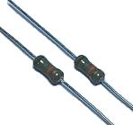 When the polarity with the input voltage changes, the electric charge of the timing capacitor is making discharge with the hysteresis prevention circuit. These are the resistors to apply the electric current to the diodes for the electric charge of the capacitor to make discharge. The 1/2-W resistor is used. 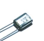 This is the capacitor to shift the phase of the pulse to apply to the gate of the triac. I am using the polyester film capacitor of 0.1 µF 50 V. There is not polarity. 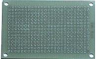 I used the one of 15 halls x 25 halls. The universal printed board 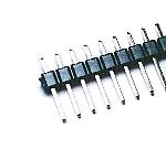 This is the terminal to connect the cable of the input and the output. It is not necessary to use the one of this shape. Also, if connecting the wire with direct to the printed board, it is not necessary to use this terminal. 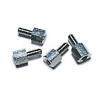 I use this to install the printed board to the case. There is not necessity of the metal. I used the one with the 5-mm height for the 3-mm screw. |