Circuit explanation
of PLL synthesizing oscillator(2)
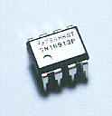
The comparison frequency which is inputted to MC145163 is mixed with 119.3MHz by SN16913 and becomes 14MHz to 16MHz. Because the phase comparison frequency is 10KHz, the dividing range of the comparative divider becomes 1400 to 1600. The BCD specification value of 103 is fixed on 1 and the BCD specification value of 102 is made to be able to choose 4 or 5. The BCD specification value of 102 becomes 0100 or 0101 when it is displayed by bits. The bit of 20 is made to be able to be changed into 0 or 1. 101 and 100 specify 0 to 9 by the binary-coded decimal code. The frequency of 200 channels can be specified by the 10KHz unit by above dividing ratio specification.
C3 and C4 become the capacitors of the Colpitts circuit for the voltage division. The oscillation frequency is changed by the capacitance of C5, D1 and D2.  D1 and D2 are the variable capacitance diode (the varicap diode). The capacitance of the diode changes when gaining opposite direction voltage. The capacitance becomes small when making opposite direction voltage high. D1 and D2 are the variable capacitance diode (the varicap diode). The capacitance of the diode changes when gaining opposite direction voltage. The capacitance becomes small when making opposite direction voltage high.
This time, it mixes 133.3MHz - 135.3MHz of frequency of the VCO and 119.3MHz of the outside oscillator and it is outputting 14MHz - 16MHz. When mixing, added frequency (252.6MHz - 254.6MHz) is output too. Because it isn't possible to handle a 200MHz frequency in MC145163, 14MHz - 16MHz are used as the input.
Two the same circuits are preparatory as the output buffer. One is used for the transmitter and the other one is used for the receiver. The FET transistor is using for the output buffer. The FET is an electric Field Effect-type Transistor. The output current (the drain electric current) can be controlled at the voltage which is gained by the input (the gate). Usual transistor controls an output current in the electric current which flows through the base. In case of the FET, because to pass an input electric current isn't necessary, it is possible to compose with the simple circuit. |