Parts explanation
of the temperature controller
of the bending apparatus
 This transistor is used with the thermistor voltage converter and the relay drive circuit.  I used LM319 as the voltage comparator. The other comparator is OK.  This is the regulator IC to make the 9-V voltage which was stable from the 12-V power supply. I used the type which it is possible to apply the 100-mA output current to.  As for the resistor of the temperature control circuit, 1/8 W are used. As for the resistor of the electric power control circuit, 1/2 W are used.  These are the capacitors to bypass the alternating current signal which is applied to the input of the voltage converter and the comparator to the ground. At the circuit this time, the alternating current signal is the unnecessary signal which becomes the malfunction of the equipment. I used the multilayer ceramic capacitors for the bypass capacitors. 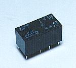 I used G5V-2 which is made by the Omron company. The one that the drive voltage is DC 12 V is used. There are two sets of points of contact and each is the following specification. 125V AC : 0.6A 110V DC : 0.6A 30V DC : 2A 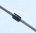 Because it is, when making the relay the OFF condition, the high voltage sometimes occurs. This diode is put to protect for this voltage not to break the transistor. This time, because the power supply voltage isn't high, even if it doesn't put this diode, the transistor doesn't break. I put for the safety. 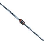 This time, the trigger diode which I am using is N413 which is made by NEC. The breakover voltage (VBO) of N413 is up to 40 V from a minimum of 26 V according to the data sheet. Because there is not polarity, it is OK even if you install in any direction.  This is the capacitor to shift the phase of the pulse to apply to the gate of the triac. I am using the polyester film capacitor of 0.1 µF 50 V. There is not polarity. 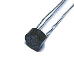 I used the diode bridge for the diode of the hysteresis prevention circuit. I used the one of the maximum voltage of 200 V, and the maximum forward direction electric currents of 1.5 A. As for the flowing electric current, because it is little, the one with the smaller capacity is OK. It is necessary to be careful so as not to make a mistake in the connection of the pole. The four diodes can be used instead of the diode bridge, too.  I used the one of 15 halls x 25 halls. The universal printed board  This is the terminal to connect the cable of the input and the output. It is not necessary to use the one of this shape. Also, if connecting the wire with direct to the printed board, it is not necessary to use this terminal.  I use this to install the printed board to the case. There is not necessity of the metal. I used the one with the 5-mm height for the 3-mm screw. The metallic studs are used to connect the ground wiring on the printed board with the case. |