as used in Pinball.
04/03/05 - by mailto:cfh@provide.net?subject=pinball_connectors.
Information gathered from Molex.com, talking to Molex technical advisors, and [name removed by request] (an eight year automotive wiring industry Manufacturing Engineer, who worked for three years as supervisor of the wiring crimp die engineering department and four years as the Program Manager of a Vehicle Wiring Program for an automotive wiring company in Detroit). Most pictures by Molex.
Table of Contents.
- Connectors Explained (Introduction)
- When are Connectors Worn Out?
- Connector Tools & Parts Needed, and Where to Get Them
- How to Perform a Good Connector Crimp
- Should Connector Terminal Pins be Soldered?
- Converting Looped IDC Terminal Pins to Crimped Pins
- Removing Connector Terminal Pins
1. Connector Introduction.
Why Use Connectors?
You don't need a connector to complete a circuit. You could solder components
together. However, imagine the effect soldering would have on assembly
manufacturer, repair and upgrades. Using connectors offers several important
advantages over permanent connections.
-
Connectors improve manufacturing:
Connectors make it easier to assemble electronic products. They also facilitate mass production processes.Connectors ease repairs:
If an electronic component fails, connectors allow a technician to quickly replace it with a new one.Connectors permit upgrades:
As technology advances, connectors allow us to replace old components with newer, more sophisticated ones.Connectors allow design flexibility:
Connectors give engineers the flexibility to design and integrate new products and components into existing systems.
Housing.
Usually made of molded plastic, a housing is a connector's casing. Its main
functions are to hold the terminals and protect them from shorting, dust,
dirt, moisture, and electrical interference.
Terminal Pins.
Terminals are the metal components in a connector that conduct current. They
are also known as contacts, and they are usually either male or female, as
shown on the right. You may hear certain types of male terminals referred
to as leads or posts. Terminals are inserted into connector housings. When
the connectors mate, the terminals meet and bridge the circuit path.
Methods of Termination.
Termination is a key concept in connector design. It refers to the method
used to join a terminal and a conductor. Good termination assures sound
electrical contact and maximum strength between the conductor and the terminal
(for a gas-tight connection, to prohibit corrosion). The most common termination
methods are listed on the right and discussed on the next few pages
- Crimping: What all replacement pinball connectors should use. Also utilized by many others, especially the auto industry.
- Insulation displacement: What many pinball manufacturers originally used.
- Surface mount: hi-tech electronics industry.
- Wire wrap: for prototyping.
- Soldering.
- Press fit.
Termination–Crimping.
In crimping, a metal sleeve is secured to a conductor by mechanically crimping
the sleeve with pliers, presses, or automated crimping machines. Note that
the conductor is crimped in two places – on the wire and on its insulator.
The latter is called a strain relief. It provides additional resistance to
mechanical stress. A "good crimp" provides a gas-tight connection on the
terminal pin, which prohibits corrosion at the wire to terminal pin connection.
Since a crimped connection can be easily performed with an inexpensive hand
crimper, and provides an excellent gas-tight connection, this is what should
be used on most replacement pinball applications.
Crimped connectors also work well in a production environment. Molex makes automatic crimping tools and dies, which can feed terminal pins and wires, doing many many crimps automatically per minute. After talking to the Molex tech advisors, they admitted this: "Hand crimpers are a necessary evil. We don't like them, and wish we didn't have to sell them. They can provide inconsistent crimps, with the possibility of human error. And they can make our highly engineered products fail when they should not fail, if machine installed." So keep that in mind when hand crimping! The end result is all up to you (below is a guide to proper hand crimping.
Termination–Insulation Displacement.
In insulation displacement technology (IDT or IDC), an insulated wire is
pressed into a terminal slot smaller than the conductor diameter, displacing
the insulation to make electrical contact. In application, insulation need
not be removed, which is a major advantage of this method of termination
using Insulation Displacement Connectors (IDC). That is, the advantage to
IDC connectors is that assembly time is dramatically reduced, decreases cost.
This is why most pinball manufacturers used this (crappy!) style of connector
termination originally. IDC connectos are not used for reliability, they
are used to decrease assembly cost. Hence as a replacement, this style connector
should be avoided.
IDT/IDC connectors are great for manufacturers. There's no separate step of stripping the wire for connection to the terminal pin, and no crimping step. Basically the only connection step involved is mating the wire to the IDT connector and pressing it in place. In the short time, an IDT connector works fine. But over time, due to the design of IDCs, the "V" that cuts through the wire insulation can also eventually cut the wire strands too (causing a decrease in current handling, which means a burnt connector!) Also the wires can be pulled/ripped from the IDC terminal pin much easier than a crimped connection. And lastly, the tool required to do a good non-production IDT connection is expensive, compared to a hand crimper (I'm not talking about that small IDC mushroomed shaped tool).
IDT/IDC versus Crimped Connector Current (Power) Ratings.
Molex and Panduit (Panduit was used by Williams Electronics on their WPC
pinballs) IDC connectors are rated at 7 amps and 8 amps respectively with
18 gauge wire. But this rating is for 20 degrees C (68 degrees F). At 25
degrees C (room temperature), they are rated at 7.5 amps. And current
capabilities drop fast as the temperature increases. Most electronic pinballs
operate at least at room temperature, and usually much warmer. At 60 degrees
C they are rated at 4.5 amps. At 75 degrees C they are rated at less than
4 amps. Why does current capability drop off so quickly? The contact to wire
connection is the problem. The IDC contact to wire is four small surface
area positions, and this leaves no room for thermal expansion. (Compare this
to the contact to pin connection, which is only slightly affected by thermal
expansion.) Now look at crimp-on connector. These are rated at 7 amps, but
they will handle 7 amps all the way to 75 degrees C. Crimp-on connectors
do not have the contact to wire thermal expansion problem that the IDC contacts
have. Note crimped Molex Trifurcon connectors do not handle any more current.
But they do have a big advantage - they are much more vibration resistant,
and maintain their current handling much better than single wiper connectors.
Pitch.
Pitch is the distance from center-to-center between adjacent conductors.
Pitch also affects arcing, which can cause interference between adjacent
conductors in a connector. The most common pitch size used in pinball is
.100" (for low voltage data) and .156" (for power connections).
Connector Levels.
There are many types of connectors. However, each type fits into one (or
more) of five categories. In the industry, these categories are known as
levels. The levels were defined by major connector companies under the auspices
of an organization called NEDA.
- Wire-to-Board or Subassembly-to-Subassembly Level (common pinball usage).
- Box-to-Box or Input/Output Level (also used to a lesser degree in pinball).
- IC Chip or Chip-to-Package Level.
- IC Package or Package-to-Board Level.
- PC Board-to-Board Level.
Signal and Power Connectors.
There are two broad types of connectors: signal and power. They are often
distinguished by the amount of power they carry. But the key distinction
is that signal connectors have minimal resistance to current flow. This minimizes
disruption of the relatively weak signals flowing through them.
A disk drive uses both signal and power connectors. The power connector bridges the circuit that drives the unit. Because the power current is so strong, a small loss is acceptable. The signal connector, however, carries data in very weak signals. The connector is therefore designed to eliminate signal loss.
Conductors and Insulators.
Electrical charge moves through some materials better than others. Substances
through which electrons flow freely are called conductors. Substances that
resist the flow of electrons are called insulators. In the electronics
industry, a more common term for insulator is dielectric.
Copper wire is an excellent conductor because it has a large number of free electrons. If a copper wire is connected between the terminals of a battery, free electrons in the wire move from the negative terminal to the positive terminal. This free flow of electrons is electric current.
Terminals as Conductors.
In a connector, current is conducted through the connector by the contacts
or terminals, which are made from various metals. Metal is one of nature's
best conductors because it has a lot of free electrons. When two metal terminals
mate, electrons can flow from one surface to the other, continuing the circuit.
Insulators in Connectors.
Plastics are used in connector housings because of their excellent dielectric
properties. Like all good insulators, plastic resists the flow of electric
current. The electrons of an insulator are tightly bound to their atoms and
cannot move freely, even if you apply an external charge. Other common insulators
are glass and rubber.
Voltage.
Voltage is a force that pushes electric current through a circuit. It causes
electrons to jump from one atom to another. Voltage is often referred to
as electric pressure, and is indicated by the V symbol. Typical connector
voltages are 50V, 125V, 250V, and 600V.
This dammed river image is often used to explain electrical measurements. Voltage is like water pressure. No force actually pushes electrons through a circuit. Rather, like the water level, the difference between the two levels forces the flow. The greater the discrepancy between levels, the greater the flow.
Current Rating and Amperage.
Current rating indicates the rate of flow of electricity. It is measured
in amperes and is indicated by the letter A. In a connector specification,
this figure indicates the maximum amperes at which the connector can be used
continuously without electrical or mechanical failure.
Amperage is similar to gallons per minute or gallons per second. It indicates how much electric current flows past a certain point in a given time period. Connector current ratings are usually in the range of 1A to 50A per circuit.
Resistance and Ohms.
Resistance is a material's tendency to inhibit electron flow. Resistance
is measured in ohms. This specification indicates the maximum resistance
of the contact area when the connector is mated. Typically, this is less
than 25 milliohms.
In the water example, resistance is caused by the valve. Tighten the valve and the rate of flow decreases. In a conductor, resistance is a property of the material. It occurs when electrons collide with atoms and give up energy. A conductor like copper has low resistance.
The Relationship between Voltage, Resistance, and Current.
It's important to understand that voltage, resistance, and current are not
independent of each other. They have an intimate relationship. Their relationship
is expressed by Ohm's Law. When selecting a connector, all three must be
considered and matched to the application.
Ohm's Law: the current in an electrical circuit is directly proportional to the voltage and inversely proportional to the resistance. Voltage = Current x Resistance, or Current = Voltage/Resistance.
The important point about Ohm's Law is that, when selecting connectors, all the electrical specifications must be considered. All metals have inherent resistance. The greater the resistance, the more voltage is required to push the current through the connector. Using Ohm's Law we can determine the overall efficiency of a connector.
Mechanical Specifications of Connectors.
The mechanical specifications of a connector indicate how a connector performs
under critical mechanical actions. These are of great importance to customers
who must match the right connector to an application.
-
Contact Insertion Force.
This specification identifies the mechanical force required to insert a terminal into a connector housing.
-
Contact Retention to Housing.
Contact retention force holds a terminal in a housing cavity. This prevents terminal backout, or the coming loose of the terminal. Typically, locking devices called tangs secure the terminal against the housing walls using spring-like pressure. The contact retention to housing specification describes the force required to remove a properly seated terminal.
-
Wire Pull-Out Force.
This specification describes the force required to separate a wire from a terminal by pulling them apart. This is primarily a function of the termination method and the quality of the termination. In a crimped terminal, for example, both the insulation and conductor are crimped to assure maximum wire pull-out force.Mating and Unmating Force.
This specification describes the force required to join and separate two halves of a connector. This is the sum of contact mating forces plus any additional force necessary to overcome minor misalignment of connector halves and any dimensional variations in the housings.Normal Force.
Once terminals are mated, normal force is the pressure applied perpendicular to the terminal interface. This pressure assures a gas tight condition between the terminal surfaces. This is considered the most important mechanical specification because it assures a consistent and high quality electrical contact.
Durability of Terminal Pins and Header Pins.
Durability indicates the number of times a terminal can be mated and unmated
without degrading performance. Durability is measured in "cycles" (the number
of times a connector can be removed or installed). As shown above, durability
varies with the materials used.
The typical pinball connector (tin plated) has a life of 25 cycles. That's pretty low! But after 25 insertions or removals, the terminal pin's plating and retention (ability to retain shape) are compromised, and reliability will suffer. Header pins also have the same problem with plating (but not retention!) Add vibration into the formula, and the cycle life is probably even lower.
If pinball manufacturers had used gold plated parts, the terminal pin life would be up around 100 cycles. But gold parts cost more, and pinball machines have an expectant operating life of five years (having a longer life than five years could limit sales of future games!) This is the reason why cheaper "25 cycle" terminal pins are used by pinball makers. Connectors are probably the biggest single problem in solidstate pinball machines (of any pinball manufacturer). So in a way, shorter connector life is a "built-in timer" to limit the reliable life of electronic pinball games, hence keeping operators from profitable running a pinball machine for greater than five years.
If a pinball machine is over five years old, chances are *really* good it will need at least some connector replacement! If the General Illumination (GI) 6 volt connectors are not burnt, chances are good they have been stressed. Also the power connectors handling the +5 volt logic and +12 volts probably need some attention too. There are really no exceptions to this rule! If a game is to run reliably, replacing these connectors (at minimum) will probably be needed. If a game is even older than five years, I can almost guarentee the user will be doing some sort of repair to the connectors. It's just a matter of time.
Stamping Materials.
Terminals and pins are made of a variety of metals, each with different
properties. Because of their atomic structure, metals are excellent conductors
of electricity. Metals also have mechanical properties that make them ideal
for connector terminals.
The properties of metals that are of interest to connector manufacturer are:
- Electrical conductivity
- Mechanical strength
- Formability
- Resilience (ability to return to its original shape after slight deformation)
| Common Metals Used in Molex Terminals
|
|
Plating.
Metals that have good mechanical properties do not always have ideal electrical
properties. Plating is the process of coating terminals of base metal with
a layer of nickel, tin, or gold to improve their electrical performance.
Common stamping metals include brass, phosphor bronze, beryllium copper, and other copper-based alloys. As you have learned, these metals have good strength, spring, and formability. Yet each of these metals has electrical deficiencies. To overcome these deficiencies, terminals made from them are plated with gold, tin and tin-based alloys, and palladium/nickel alloys.
Copper-based alloys have ideal mechanical properties, but they do not meet other connector design requirements. They are plated to improve:
- Electrical performance
- Solderability
- Corrosion protection
Most pinball connector pins are made of brass. But phosphor bronze is a better choice for power circuits like General Illumination (if available in the pin desired), as it has higher current rating. Beryllium copper is also good, but often not available for the terminal pins needed.
For example, for .156" trifurcon terminal pins series 6838, here is a comparison of brass versus phospher bronze current (amp) ratings:
| Wire Guage | 18 | 20 | 22 | 24 | 26 |
| Phospher Bronze | 7.00A | 6.25A | 5.50A | 5.00A | 4.50A |
| Brass | 5.00A | 4.75A | 4.50A | 4.25A | 4.00A |
Trifurcon Terminal Pins.
The Trifurcon design provides three distinct points of contact from the terminal
pin (above left) to the header pin (above right). This is the ideal choice
where high shock or vibration exists. For low current/voltage, Gold is
recommended (contact factory). Phosphor Bronze recommended for higher rated
current circuits. Trifurcon only available for .156" and larger pitch. Because
Trifurcon connectors resist vibration, they maintain their current (power)
ratings much better than single wiper connectors. For this reason Trifurcon
crimped connectors are ideal for pinball applications.
Plating and Corrosion.
Recall that corrosion is the deterioration of a metal due to exposure to
moisture or other contaminants. This is a key concern of connector designers.
If voltage or wiping pressure is high, a corrosive layer is easily penetrated.
But in low voltage situations, even slight corrosion can obstruct current
flow. Plating materials such as gold are chosen for their high resistance
to corrosion.
Metals vary in their resistance to corrosion. The relative corrosion resistance of different metals varies, from aluminum, which corrodes easily, to gold, which does not corrode at all. The list below shows from top to bottom, metals which corrode easily (1) to metals that do not corrode at all (10):
|
|
| Common Plating Metals |
|
Tin versus Gold Plating.
Terminals plated with tin or tin alloys oxidize and are contaminated by gasses,
water vapor, and organic molecules. This film degrades conductivity, so
sufficient wiping pressure must be applied to break the film. This pressure
also removes tin plating, which decreases durability. Gold Plating Oxide
film does not form on gold, so wiping pressure can be lighter to penetrate
only the contaminants. Durability is much higher, often in the hundreds of
cycles. This is why modular phone jack terminals, which may be mated and
unmated many times, are usually gold plated.
Selective Gold Plating.
The process used to plate gold only in selected areas of a terminal. Selective
plating assures that critical terminal areas are plated, but non-critical
areas are not. This reduces costs.
Do NOT Mix Gold and Tin Terminals and Headers!
It is not a good idea to mate a gold terminal to a tin header (or vice versa),
or mix any other dissimilar connector metals. Use the same metal for both
contacts! The contact resistance will go up with dissimilar metals, causing
all sorts of problems (depending if it is a logic connector or power connector).
This exact problem has been seen in the automotive industry. Though no cars
have been recalled because of this (that I know of), there have been numerous
"engineering actions" and "service bulletins" because connectors have mixed
gold and tin parts.
2. When are Connectors Worn Out?
Failing connectors can cause a great number of problems in solidstate pinball games (1977 to present). For example, random game resets (where the game seemingly turns itself off and back on during a game), game lock-ups, coils and switches and lamps that don't work, and other random and unpredictable behavior are largely attributed to failing connectors.
Re-Seating Connectors - the False Hope.
A good many pinball people will try and "fix" these problems by doing a connector
"re-seat". That is, they will remove and reinstall the questionable connector
in an attempt to "fix" the problem. Unfortunately, this does *not* fix the
problem! Connector re-seating is a great way to identify a connector problem.
If the problem goes away with a "re-seat", that means the connector needs
to be replaced. But the re-seat itself does not fix the problem. The only
way to fix the problem reliably is to replace all the connector parts involved.
The Five Year Life Span.
The style of Panduit and Molex connectors used in pinball generally have
a 25 "cycle" life span (a "cycle" is one removal and re-installation of a
connector). And frankly, after as few as five cycles, there could be problems
because of the high vibration pinball environment, the reduced terminal pin
tension, and the age of many games. Frankly, these connectors, chip sockets,
and the games themselves were only manufactured to have a five year life
span. This was done (intentionally or unintentionally) by the manufacturer
to ensure the games "broke" (or became a unreliable, i.e. a "pain in the
butt") after five year, so operators would buy new games. This is call "planned
obsolence", or "job security" for the amusement industry. Because successful
games that earned well and didn't break for more than five years were *hated*
by the industry that created them!
Re-Seating Five Times to "Clean".
The other false "repair tip" heard among many repair people is to "reseat
a solidstate connector five times to 'clean' it". This is not only a bad
idea, but it just makes things worse (because it eats up five cycles in the
connector's already short 25 cyle life span). Again the reseat priniciple
is great at IDENTIFYING a connector problem, but it does NOT fix anything!
The except to the reseat rule involved gold plated connectors. These have a much lower terminal pin tension, and a higher 100 cycle life. In the case of gold connectors, the "re-seat to clean/fix" is acceptable. But gold connectors are rarely used in pinball (ribbon cables are the only gold plated connectors used in pinball). But if the connector in question is a .156" or .100" Molex connector, I don't care how old/new the game is, if re-seating "fixes" the problem, that connector needs to be replaced! No if's, and's, or but's.
Gas Tight Seal.
For a connector or socket to be reliable, it *must* have a "gas tight" seal
(air tight, but the connector industry calls it "gas tight"). In the situation
of pinball, nearly all connectors/sockets are tin on tin. To keep tin on
tin gas tight, a fair amount of terminal pin tension is required against
the male pin. The amount of tension needed has to do with the corrosion
properties and wear properties of tin.
If the gas tight seal is compromised on a tin on tin connector/socket, corrosion works on the junction, and an intermittent connection is the result. This corrosion is usually the result of either:
- Decreased pin pressure (too many cycles and/or too much vibration).
- Worn parts (the tin plating is worn from too many cycles and/or too much vibration, and does not protect against corrosion like it once did).
Reseating does NOT fix the lack of a gas tight seal on tin on tin connectors or sockets! If corrosion has started, re-seating does not fix this. All it does is temporarily "fix" it, until corrosion comes back (and it WILL come back!) A connector/socket that works after re-seating is telling the repair person something ("replace me!") My suggestion is to listen to the game.
3. Connector Tools & Parts Needed, and Where to Get Them.
I can't think of any solidstate 1977 or later pinball machines that I have worked on that have not needed some sort of connector repair! With this in mind, certain tools and parts should be in every pinball mechanic's toolbox to make the job better and easier (no, needlenose pliers can *not* be used to crimp connectors!) There's no cheap way to do this. The right tools and parts are needed, so just honker down and buy them.
Tools Needed.
Here are the minimum connector tools required.
-
Terminal Pin Hand crimper. These are used for all the different styles of
Molex terminal pins.
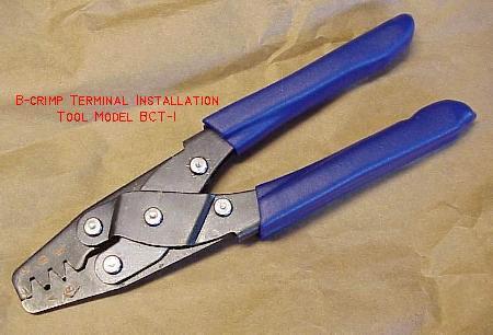
- Aeroelectric's terminal tool BCT-1, available from here (about $32, good for all pin sizes) is an excellent crimper,
- Molex crimper #11-01-0185 (type 1 specifically designed for .100" terminal pins, 22-30 guage wire).
- Molex crimper #63811-2200 (type 1 specifically designed for .156" terminal pins, 18-24 guage wire).
- Molex crimper #63811-1000 (type 6, inexpensive but versatile, 14-24 guage wire).
- Molex crimper #11-01-0015 (type 3, excellent but more expensive, 18-24 gauge wire, discontinued).
- Waldom/Molex crimper WHT-1921 (good yet inexpensive, for .100"/.062" and .156"/.093" pins).
- Waldom/Molex crimper WHT-1919 (really for .156"/.093" pins only).
- Amp 725 (probably no longer available).
- Radio Shack #64-410 (last resort, not very good and not recommended).
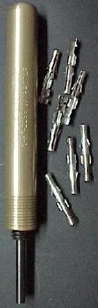
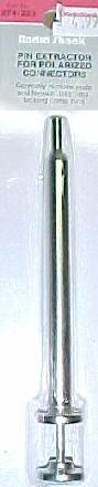
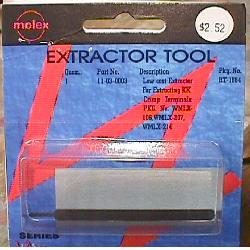
- .093" Round Pin Extractor: Molex part number 11-03-0006, or Waldom/Molex part number WHT-2038, or Radio Shacks part number 274-223 (in this case the Radio Shack tool is pretty good).
- .062" Round Pin Extractor: Molex part number 11-03-0002, or Waldom/Molex #WHT-2285. Optional, as this size is not used nearly as much as the .093" size.
- .156" terminal pin extraction tool from card edge connector housings: Used mostly for Gottlieb system80 games. Made of spring steel, Molex part number 11-03-0016 (rubber handle version), or Molex #11-03-0003 (bare bones version).
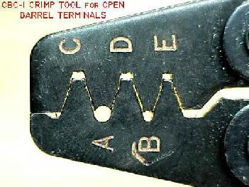
| The BCT-1 hand crimper's
different jaw sizes for different size connector pins. The "C", "D", and "E" pockets are used to crimp the bare wire to the Molex connector pin. These pockets cause the end of the pin's wire grip wings to curl over and dive into the center of the wire strands. Pockets "A" and "B" have a smooth circular shape, and can be used to crimp the terminal pin's insulation-grips into a "bear hug" around the wire's insulation, but Molex suggests using the C,D,E pockets for insulation too. Picture by aeroelectric.com |
 |
| Left:
Molex/Waldom .093" pin extractor #WHT-2038. Middle: Radio Shack .093" pin extractor #274-223. Left: Molex spring steel card edge extractor #11-03-0003. |
 |
-
Molex Connector Parts to Keep On-Hand for Pinball Applications.
The following are standard Molex connector parts commonly used in pinball machines. Panduit connectors can also be used, but they are very hard to find and more expensive. Note there are some game specific Molex connectors (such as Gottlieb system80 double sided edge connectors, and Williams system3 to system7 interboard connectors) that are not listed here, because they are specific to only those games. The parts below are used in nearly every solidstate pinball machine. All the below terminal pins and housings are the crimp-on variety. If the game being repaired uses IDC connectors, to utilize the more robust crimp-on connectors, the plastic housing will probably need to be replaced in addition to the housing terminal pins and male circuit board header pins. If you want to buy a minimum of parts, buy the largest header and housing sizes available and cut to the size needed.- .156" header pins Molex #26-48-1155 (15 pin, with lock, cut to size).
- .156" plastic housings Molex #09-50-3151 (15 pins).
- or .156" plastic housings Molex #26-03-4151 (15 pins). This particular housing is less expensive, and specially designed for Trifurcon terminal pins.
- .156" plastic housing polarizing pins Molex #15-04-0219.
- .156" Trifurcon connector terminal pins Molex #08-52-0113 (the replacement pin of choice, used extensively in pinball; buy lots of these). Phoshor Bronze material.
-
.156" connector terminal pins Molex #08-52-0072 (non-Trifurcon, used far
less often and not as good as Trifurcon, but still needed in some situations).
Only buy these as needed.
* bold text denotes the number of pins, in this case, 15. - .100" header male pins Molex # 22-23-2121 (12 pins, with lock, cut to size).
- .100" plastic housings Molex # 22-01-3127 (12 pins, cut to size).
- .100" plastic housing polarized pin Molex # 15-04-9210.
-
.100" terminal pins Molex
# 08-50-0114.
* bold text denotes the number of pins, in this case, 12. - .093" round female terminal pins Molex #02-09-1119.
- .093" round male terminal pins Molex #02-09-2118.
Where to Buy This Stuff.
All the above Molex connector parts are available from the retailer listed at the parts and repair sources web page. Note for Mouser part number (which can be viewed/ordered on Mouser's web page), just add a "538-" before the Molex part number listed above (for example, "538-08-52-0113" is the Mouser part number for Trifurcon Molex terminal pins, as "538" is Mouser's manufacturer number for Molex). The above connector parts are also available from other source. Check out the parts & repair sources web page for details.
4. How to Perform a Good Connector Crimp.
Info from www.molex.com/tnotes/crimp.html, but re-edited, modified, and embelished with emphasis on hand crimping and pinball applications. All pictures from Molex.
You've made it through all the pinball and connector manuals, and found the replacement connector that meets your pinball's application. It has the right current rating, voltage rating, circuit size, pin size, engagement force, wire AWG capabilities, configurations, termination method, positive locks, fully-isolated contacts, and polarization, it is the perfect replacement connector.
But don't let out a huge sigh of relief quite yet - especially if the connector chosen uses a crimp termination system. While this can be one of the fastest, most reliable and rugged termination methods, if the terminal isn't crimped onto the wire correctly you can forget all about the hard work put into finding the right connector. Although there are many common crimping problems that can reduce the reliability of a pinball machine, these problems are easy to avoid with a little knowledge and advance planning.
| The BCT-1 hand crimper
for crimping Molex connector pins. Picture by aeroelectric.com |
 |
-
Before proceeding, you'll need some sort of hand crimper. Several hand crimpers
are available from Molex and other sources. See the section
above for details on that. But now that you have the
proper hand crimping too, it's time to talk about how to use it properely
to make a "good crimp". To begin with, it helps to understand that a terminal
has three major sections: Mating, Transition and Crimping.
-
The Mating section, as the name implies, is the section of the terminal that
mates, or becomes the interface, with the other half of the connection. This
section was designed to mate with a terminal of the opposite gender and to
perform in a certain manner by the connector design engineer. Anything done
that deforms the Mating Section, especially during the crimping process,
will only reduce the connector's performance.
The Transition Section is also designed so not affected by the crimping process. Here again, anything done that changes the position of the Locking Tangs or Terminal Stop affects the connector's performance.
The Crimp Section is the only section that the crimping process is designed to affect. Using a good quality hand crimper, the crimp section is deformed so it can be securely attached to a wire. Ideally, all the work done to crimp a terminal onto a wire occurs only in the Crimp Section.
An example of a properly performed crimp is seen below:
-
In the picture above, the insulation crimp compresses the insulation without
piercing. The wire strands (or brush) protrude through the front of the conductor
crimp section by at least the diameter of the wire's conductor. For example,
an 18 AWG wire would protrude at least .040". Both the insulation and conductor
are visible in the area between the insulation and the conductor Crimp Section.
The conductor Crimp Section shows a bellmouth shape in the leading and trailing
ends, while the Transition and Mating Sections remain exactly the same as
they were before the crimping process.
If a crimped terminal does not look like the terminal in the above illustration, the problem was probably caused by something that went wrong during the crimping process. Below are the most common problems that may occur during the crimping process, and how to avoid them.
Crimp Height is Too Small.
The crimp height, which is the cross sectional height of the conductor Crimp Section after it has been crimped, is the most important characteristic of a good crimp. The connector manufacturer provides the crimp height for each wire size for which the terminal was designed. The correct crimp height range or tolerance for a given wire may be as small as 0.002".With a specification this tight, getting a perfect hand crimp can be difficult. And forget measuring the crimp height; terminal geeks would measure this with a "point micrometer", something I can guarentee you don't have in your pinball toolbox!
But still, the information is good to know. So keep in mind that an over-crimped terminal (crimp height too small) is just as bad as an under-crimped (crimp height too large) terminal.
-
A crimp height that is either too small or too large will not provide the
specified crimp strength (terminal retention to the wire), will reduce the
wire pull out force and current rating, and may generally cause the crimp
to under perform in otherwise normal operating conditions. A crimp height
that is too small also may cut strands of the wire or fracture the metal
of the conductor crimp section.
Crimp Height Too Large.
A crimp height that is too large will not compress the wire strands properly. This causes excessive voids in the Crimp Section because there is not enough metal-to-metal contact between the wire strands and the metal of the terminal. This also compromises the Gas Tight seal that a good crimp offers.The solution to problems the above problems is very simple: adjust the conductor crimp height. With a hand crimper, either press harder or lighter to adjust the crimp. Also make sure the right crimper is being used (remember there is a different hand crimper for .100" and .156" terminal pins).
Crimp Width.
Crimp width is just as important as crimp height. For optimum crimp performance, the cross sectional area needs to controlled. For the most part, the crimp tool geometry will produce the proper crimp width, when the terminal is crimped to the recommended height. This assumes you're using the manufactures recommended crimp tool. If using a different crimp tool, the width may be incorrect. Therefore, the resultant cross section will be too large or too small.So what's the bottom line here? Buy a Molex (or Waldom) hand crimper designed for .156" or .100" terminal pins. This will ensure a better hand crimp.
Insulation Crimp Too Small or Too Large.
Connector manufacturers do not typically supply a crimp height for the insulation due to the variety of insulation types and thicknesses. The insulation crimp provides a strain relief for the conductor Crimp Section so that as the wire flexes, the wire strands do not break. An insulation crimp section that is too small may overstress the metal in the insulation Crimp Section, weakening the strain relief function (and potentially breaking the wire).Most types of production crimp tooling allow the insulation crimp height to be adjusted independently of the conductor crimp height. The correct adjustment allows the terminal to grip the insulation for at least 180 degrees without piercing the insulation. An insulation displacement, or compression where the outside diameter (OD) of the terminal's insulation crimp and the OD of the insulation are approximately the same, is ideal.
-
Loose Wire Strands
Loose wire strands are another common cause of crimping problems. If all the wire strands are not fully enclosed in the conductor Crimp Section, both the strength of the crimp and the current carrying capability may be greatly reduced. To get a good crimp you need to meet the crimp height the connector manufacturer specifies. If all the strands are not contributing to that crimp height and therefore crimp strength, the crimp will not perform to specifications. Generally, the problem of loose wire strands is very easy to solve by simply gathering the wires back into a bunch before inserting them into the terminal to be crimped. Using a "strip and retain" process for insulaton removal, where the insulation slug is not completely removed from the wire until it is ready to have a terminal crimped onto the wire, helps minimize the problem (yea right, now who does that?)
-
Too Short Strip Length
If the strip length is too short or if a wire is not fully inserted into the conductor Crimp Section, the termination may not meet the specified pull force because the metal-to-metal contact between the wire and the terminal pin is reduced. As shown in the figure above, the strip length of the wire is too short (note that the insulation is in its proper position), not allowing the required one wire outside diameter (OD) extension in front of the conductor Crimp Section. The solution is simple: increase the strip length of the wire stripping equipment to that specified for that specific terminal.
-
Wire Inserted Too Far
Another crimping problem that relates to a too short strip length occurs when the wire is inserted too far into the crimp sections. As the figure above shows, the insulation is too far forward of the insulation Crimp Section and the conductors protrude into the Transition Section. This may cause as many as three failure modes in the actual application. Two relate to a reduced current rating/wire pull out force due to a reduction of the metal-to- metal contact in the conductor Crimp Section. A metal-to-plastic contact isn't as strong, nor does it conduct electricity, as well as metal-to-metal.The third failure mode may occur when the connectors are mated. If the wire protrudes so far into the Transition Section that the tip of the male terminal hits against the wire, it may prevent the connectors from fully seating or it may bend the male or female terminals. This condition is known as "terminal butting". Under extreme cases, the terminal may be pushed out the back of the housing even though it was fully seated in the housing.
-
"Banana" (Excessive Bending) Terminal
One of the most descriptive crimping problems is known as a "banana" crimp (figure above), because the crimped terminal takes on a banana shape. This makes it difficult to insert the terminal into the housing and may cause terminal butting. This problem is easy to solve by not squeezing the hand crimper so hard!
-
Crimp Too Far Forward
One of the more obvious crimping problems is when part of the Transition Section is damaged, as shown above. In the terminal shown, the tab sticking up is a design feature called a "terminal stop". Its function is to prevent the terminal from being inserted too deeply into the housing. If the stop is extremely damaged, the terminal can actually be pushed all the way through the housing.
-
Undersized Bellmouth
The correct size for a bellmouth (see above) is approximately 2X the thickness of the terminal material. For example if the terminal is made from material that is .008" thick, the bellmouth should be approximately .016". While a few thousands of an inch either way will not materially affect the terminal's performance, if the bellmouth is missing or if it is less than one material thickness, there is a risk of cutting the wire strands. The fewer strands that remain, the lower the termination strength.
-
Oversized Bellmouth
There is also a problem if the bellmouth is oversized (above), because this reduces the total area that the crimp section of the terminal has in contact with the wire. The less the wire-to-terminal interface, the lower the wire pull out force. If the crimp height is correct, then it is likely the problem is caused by a worn hand crimper, which should be replaced.
-
Bent Lock Tangs.
Although bent lock tangs are not necessarily the result of a poor crimping process, the connector can fail just the same. Lock tangs (see above) may be bent either in or out too far, which impacts the terminal's ability to completely lock into the shelf in the housing that was designed for this purpose. The tangs may be damaged by handling after the terminals are crimped onto the wires, or if the wire is soldered to the terminal pin (not recommended!)Rules.
While there are problems that may be caused during the crimping process, there are just four simple rules that will help ensure a successful connector application:- Choose the right connector for your application requirements.
- Use the crimp tooling specified by the terminal manufacturer (there is a different hand crimper for .156" and .100" terminal pins!)
- Properly inspect the crimp tooling to make sure it is not worn.
- Replace the hand crimping tool if worn, as the parts that displace metal conductor and insulation wear.
Since most of the problems that are reported to connector manufacturers relate to one of the above crimping problems, Molex offers an easy-to-use guide to help you avoid problems or recognize them quickly enough so that you make only good crimps. To order this guide contact Molex Incorporated, 2222 Wellington Court, Lisle, Illinois 60532, Attention: Good Crimp Drawings.
5. Should Connector Terminal Pins be Soldered?
Some field repair people feel that after a 'good crimp' is performed on a new connector, the terminal pin should be soldered to the attaching wire. Maybe they are used to dealing with 'bad crimps' or feel they need the additional piece of mind. But is this the right thing to do?
The most common aspect of connector replacement in pinball is the GI (General Illumination) connectors. These fail the most, and require replacement most often. The generally accepted crimp-on .156" terminal pin to use for GI circuits is the trifurcon style terminal pin (i.e. Molex part# 08-52-0113, Digikey part# WM2313-ND). This terminal pin grabs the circuit board's header pin on three sides instead of just one. Though the current handling capability is not increased, the vibration resistance and durability of the pin goes up dramatically.
If a trifurcon pin is properly crimped, there is NO need to solder the connecting wire to the terminal pin. The only positive aspect of soldering a properly crimped terminal pin is the "wire pull out force" goes up. Current ratings do not go up with a soldered pin compared to a properly crimped-only pin (that information is directly from a Molex technical advisor who I talked with on the phone).
Now if there is a bad or improper crimp on a terminal pin, solder can increase the performance of a crimp. For example, a gas tight crimp is critical to long term performance. If there are voids between the wire strands or between the strands and the terminal because of a bad crimp, oxides can form (oxides are of higher resistance than the clean metals). Granted, in most applications the performance increase is negligible versus an unsoldered crimp, even a bad crimp. And the potential of doing "more harm than good" is very high when soldering a terminal pin (unless the user follows the terminal soldering method outlined below).
The risk of problems when soldering a terminal pin far out-weigh the benefit in most cases. For example, Adding solder to a terminal pin can get solder on the "locking tangs", making it unflexible. This in turn can ruin the connector housing, and make the pin nearly impossible to remove.
Soldering a terminal pin can also cause the terminal pin/wire insulation joint to fail. Or in the worse case, it can melt the insulation back beyond the pin, possibly causing a short. Also, in extreme situations, Iain documents the melted plastic insulator can wick down into the wiring, and cause the wire to become a sort-of capacitor. This can cause some difficult diagnostic problems!
Another problem with soldering terminal pins (as documented by Bobukcat) is having flux wick down and end up being left on the connector surface. This can interfere with connectivity to the header pin.
Lastly, though unlikely unless extreme heat is used, the plating on the terminal pins can be damaged by soldering.
Properly Soldering a Terminal Pin (if you must!)
With the potential problems of soldering a terminal pin known, some users
may still want that additional "insurance". Or if a good crimp can not be
performed (wrong tool or wire gauge?), soldering may be necessary to overcome
the bad crimp. Molex reconizes that some user may not following their crimping
directions, and may solder a terminal pin anyway. If this is the case, here
is the ONLY terminal pin soldering technique Molex (relucantly) recommends.
This information came from John Luthy, Molex's connector product division
manager:
- Before crimping the terminal pin, tin the end of the bare wire with some solder (best method is to dip the wire end into a hot solder pot).
- Crimp the terminal properly (see the notes above!) using a good quality hand crimper (Molex WHT-1921 part# 11-01-0015, Molex part# 63811-1000, or Amp 725).
- After the wire is properly crimped, using a temperature controlled soldering station (750 degree maximum), heat the terminal pin momentarily, right where the tinned wire is crimped in the terminal pin. The tinned wire's solder should heat and reflow, spreading to the terminal pin. Do NOT add any additional solder!
Talking to Molex representatives, they really discourage any terminal pin soldering (a good crimp does not require soldering!) But if it is done, the above steps are the technique to use.
6. Converting Looped IDC Terminal Pins to Crimped Pins.
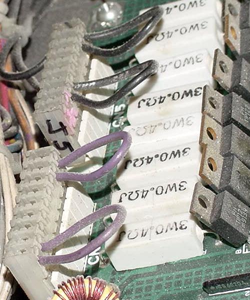
Something often seen in many Williams, DataEast and Stern pinball games from the late 1980s to the present are looped .156" Molex IDC terminal pins. This is most often seen on power pins where there is a higher amount of current coming into the circuit board, like on General Illumination connectors and main AC power connectors. A single 18 guage wire will come into a single IDC terminal pin, and then loop around to a second IDC terminal pin. The two contacts are not used for redundancy (if one pins burns for example the other is a backup), but are used to distribute the current across multiple pins. In theory the current is spread across two pins equally instead of just one pin, so each pin is handling half the current.
Looped IDC connectors on a early 1990s DataEast CPU board.
-
The looped wire is very easy to handle with an IDC (Insulation Displacement)
style connector. But unfortunately they are not so easy to deal when using
a crimped connector pin. Because IDC connectors are not a good long-term
system (as described extensively in this document above) and should not be
used when repairing connectors, we must come up with a way to convert the
looped IDC pins to looped crimped pins.
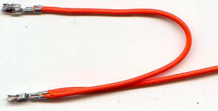
The problem is the crimped terminal pin is designed for a single 18 guage wire. Yet we must somehow get two wires into the terminal pin (to create the loop), and do a proper crimp on the double-wire pin. The best way I have found to deal with this is to looped a wire in the crimped terminal pin as seen in the picture below. Though this crimp is hardly what Molex recommends for a proper crimp (as described above in this document), I can't really come up with a better solution.
How to convert IDC looped terminal pins to crimped pins.
Picture by Ed of GPE.
-
There are two tricks to making this work. The first trick is to solder the
wires to the terminal pins as described above. That
is, lightly tin the two wires with solder before crimping them.
The key is to tin the wires very very lightly. If too much solder is applied,
the wire diameters will be too large and both wires won't fit in the single
terminal pin. Also do NOT twist the two wire together, keep them separate
and tin them separate. Then after the wires are crimped, gently heat
the wires and pin (without adding any new solder) to melt the existing solder,
securing them all together to the crimped pin.
The second trick is to use the insulation-grabbing part of the terminal pin as an added area for the stranded wires. Because the insulation-grabbing portion of a crimped terminal pin is larger, this additional area handles the two wire together fairly well, without spilling-over the stranded wires outside of the crimp. Though this is definately not how to do a proper crimp, in this situation there really is no alternative. Note a bit of practice is needed to get a feel for this "illegal" crimp.
An additional thing to remember is there's limited space inside the plastic Molex connector housing for the two wires. So a clean and tight crimp must be done. Be sure to inspect the crimp carefully for any stray stranded wires that could short to adjacent pins after the terminal pin is inserted into the plastic connector housing.
7. Removing Connector Terminal Pins.
Removing Molex terminal pins (either IDC or crimp-on varieties) is very easy. Molex makes an official pin removal tool. But frankly, I would not suggest buying it. There is an easier way.
| An "official" Molex
card edge pin extraction tool. It actually works Ok, and is made of spring steel. Molex part number 11-03-0003. There is also a Molex removal tool part number 11-03-0016 that is slightly different and *much* better and easier to use. |
|
-
The easiest way to remove a terminal pin is to use a small #1 flat head screw
driver. Look at the side of the connector, where the terminal pin's small
lock barb is seen through the side of the connector. Take the small screwdriver,
and push down on the lock barb, bending it down and out of the way. Now just
pull the wire connected to the terminal pin, and the pin should just slide
right out! It may take a couple practice tries to get the right amount of
bend on the barb (too little bend and the pin does not unlock - too much
bend and the pin gets distorted and doesn't pull out easily). Also sometimes
(especially on IDC connectors), the pin may need a small needle nose pliers
to pull it out of the plastic housing. Of course only use this technique
if the terminal pin is going to be replaced (which 99% of the time that's
why you're removing it!)
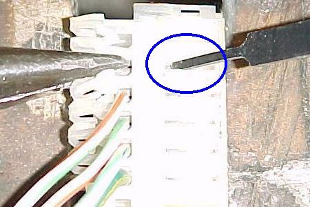
| Removing the IDC pin
with needle nose pliers after the "lock barb" was bent out of the way with the Molex tool (the blue circle shows where shows where the lock barb was bent down). Frankly it's just easier to use a small #1 flat head screwdriver instead to bend the lock barb. |
 |
-
Note this technique does *not* work for round Molex pins. In this case, a
specialized tool is definately needed to remove the round pins from their
plastic housing. There are two different round pin extractors. The one for
.093" pins is the most common in pinball (though the smaller size is also
used sometimes).
| Left: Round
Molex pin .093" extractor tool, and new crimp-on female Molex connector pins. Right: Radio Shacks' round .093" pin extractor tool, part number 274-223. |
|
|
Return to The Pinball Repair Guides.