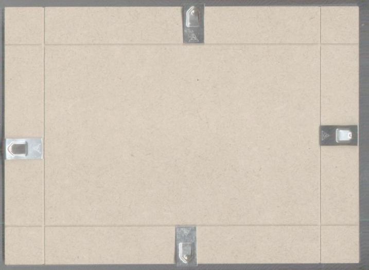
Fig . 6 backside of the photo holder
Fig . 7 Front side of the photo holder
I hope the description is clear, ah and also…Obviously you can use anything that holds the acetate sheet tight against the copper clad photo sensitised board below it.
The reason is that most chemicals in crystal form that are used in reactions release heat on dissolving. If you pour water onto a crystal of that kind, it could literally heat up and explode in your face. So always add small quantities of the above crystals to water.
The back of the paste board frame has four springy metal clips in grooves. The clips curl over to the front and hold the glass firmly.
This particular model is easy to open and remove the glass. The dimensions are far bigger than what we need, but if in the future you decide on a bigger and better circuit, this will hold them all!
Dimensions 18 x 24 cm
Now lets look at the glass-side of the holder.
I put the glass on a bit badly so that you can see it at the edges.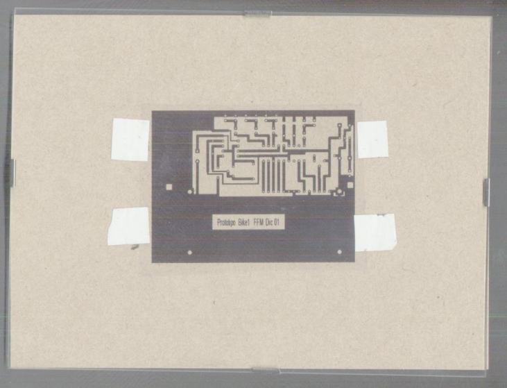
The clips are holding the glass against the base, and sandwiching the track layout. I DIDN'T put the photosensitive copper clad board under the track layout as it was also black and the contrast was very bad.
The white tags are the sticky tapes used to fix the track sheet to the photosensitive board. Pull them tight before sticking to avoid wrinkles.
I cut the board to the track sheet size with kitchen scissors, then tape on the backside of the copper board.
The Chemicals
Mixing the Chemicals
When mixing solid chemicals wear glasses if you have never done it before.
NEVER pour water onto the chemical.
ALWAYS add the chemical to the water, and in small quantities
We are going to add the chemicals to water. Normally there are no fumes from both, BUT, this depends on the purity of what you have bought, so do not mix in a closed room. Have some form of ventilation, an open window for example.
Prepare 1 litre of tap water for the NaOH and 0.25litre of tap water for the FeCL3.
Note. if you have furred kettles in your area, maybe best buy some natural water from the supermarket.
Caustic Soda solution ( NaOH)…The developer
Pour one litre of water into the plastic tray ( check that it is big enough o
hols 1 lt.)
Having weighed before hand the 0.7gm of NaOH, slowly add it to the water ,
stirring with the plastic rod.
When the solution is clear, use the funnel and pour into the bottle labelled Caustic Soda
Wash both tray and the funnel with abundant water.
Ferric Chloride solution the etchant
Pour a ¼ litre of water into the plastic tray ( check that it is big enough o hold .)
Open with care the 100gm plastic container of the Ferric Chloride crystals. slowly add the crystals to the water , stirring to aid the dissolving of the crystals with the plastic rod.
When the solution is a clear brownish yellow with no lumps on the bottom of the tray, use the funnel and pour into the bottle labelled Ferric Chloride
Wash both tray and the funnel with abundant water.
DON'T HEAT THE WATER
There is no need to heat either product to help dissolve. A normal temperature of 12 to 20 ºC for the tap water is sufficient. The colder water will take a little more time but apart from that the crystals will dissolve completely. Another reason for NOT heating is that the ferric chloride may begin to release fumes. This will not happen at normal temperatures.
The Test strip
The single sided copper clad board we have bought has a POSITIVE photo sensitive layer on top of the copper which responds to ultraviolet light. Now we are going to use normal sunlight which contains enough UV to expose the Copper clad board.
How long ? could be impossible to answer, but fortunately the test strip shown below solves this problem. The sun between 10a.m and 3 pm. Is not critical
The test strip is simply a piece of clear acetate sheet with numbers drawn on it, say 1 to 10. Use your kitchen scissors, the type that the TV advertises as being able to cut through steel). Cut a strip off the copper clad board about the same size. Mine were 10cm long by 2 cm wide. Dim the lights or draw the curtains. Peel off the protective covering of the copper clad board. Tape at the ends , the numbered acetate sheet onto the SENSITIVE side of the board ( the side you have just peeled)
Get your watch ready and a piece of cardboard big enough to cover the whole test strip .
Is it sunny? Good move the strip into the sunlight but still covered. Move the cardboard covering the test strip taped to the sensitised copper clad board and uncover ONLY the number ten for 30 seconds.
Then slide the cardboard a little more to uncover NINE for 30 seconds, then 8 for 30 seconds . Keep on uncovering each number for 30 seconds till you are at the end that is ONE is uncovered, then remove the test strip from the sunlight. Slightly cover the window to shut out direct sunlight.
Look at the test strip and the exposed copper below. You should soon see something like it.
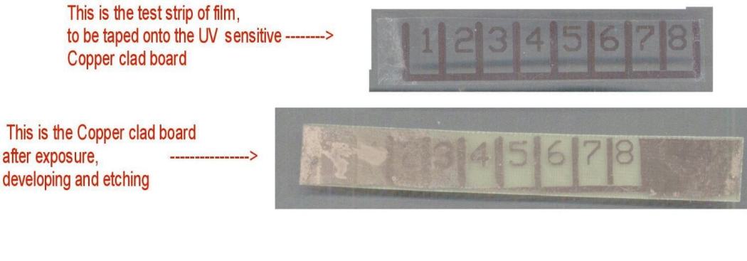
fig.8 test strips
Number 8 has had 30 x 8 seconds exposure about 4 minutes
Number 7 has had 30 x 7 seconds exposure about 3mim 30 sec
…
…
…
Number 3 has had 30 x 3 seconds exposure about 1min 30 sec … not useable
Number 2 has had 30 x 2 seconds exposure about 1min … not useable
Number 1 is completely under exposed and can't be seen
So 5, 6, 7, 8 look OK. (I used 7). The strip also indicates that the material is not critical, an exposure varied from 2.5 to 4 min makes little difference.
Getting back to the test strip you have just exposed. Peel off the acetate sheet with the numbers and submerge the test strip in the tray with the caustic soda. The correctly exposed numbers will appear within SECONDS in a slightly greyish form ( the top drawing) and the other numbers more slowly . Move the solution in the tray for a minute more or less. Then remove the copper clad board holding by the edges, from the tray and place the copper clad board under a running tap to wash off the traces of caustic soda.
Finally place the copper clad board in the tray with ferric chloride, the etchant. This is slower, it can take up to 30 minutes. But within half a minute the correctly exposed numbers will be visible, a different colour from the salmon coloured copper that is being eaten away by the ferric chloride. .
Keep on stirring once a minute or rock the board in the solution. The parts of the copper NOT covered by the numbers is gradually eaten away leaving the fibre glass board visible.
Why is there copper at each end? I had tape there and the sun didn't get to the board..
As before wash under running water for at least 5 minutes, watch your eyes and clothes.
Finally put the chemicals back into their labelled bottles. Wash everything and put the bottles out of reach of children.
Well that is the initial preparation for making the PCB. We now know how long to expose the sensitive board for.
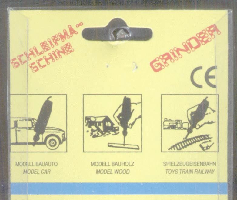
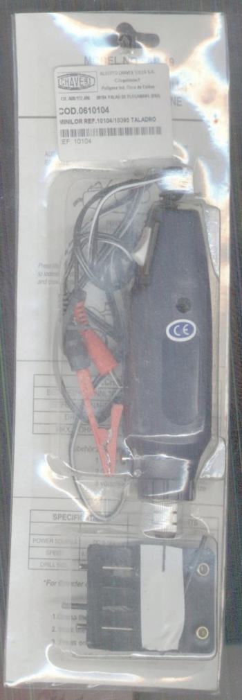
Fig. 9 the complete package, machine and a set of drills.
The drill itself is very small compared to a normal household “wall hole maker”. We need a size that will take all most standard resistor, capacitor, integrated circuit, leads and pins, to pass through the board for soldering . I think a 0.8mm drill is about right for the job , but you decide when you come to this stage, maybe you would prefer a 0.5mm. Either way they are small drills.
Now if we look at the tracks on the copper PCB carefully we see that the points we are going to drill have a round mark ( the future holes for inserting a component lead or an IC pin ), also called a pad.
When we hold the drill machine over the pad to drill through it , the drill will probably skid. To avoid the skidding and breaking the drill, get a small hammer and a nail.
Place the nail over the centre of the pad and hit its head lightly with the hammer to produce a DENT, not a HOLE in the centre of the pad.
Dent all the pads to be drilled on the board, not long, a five minute job as it is a small board.
The final problem is clamping the board . I place a piece of wood o slightly bigger than the PCB. I place it at one edge of the table and after placing the PCB on this piece of wood, screw the clamp down (protect the contact area with a doubled and then doubled again sheet of paper) to hold the paper, the PCB and the wood, firm on the table . The piece of wood is to avoid making drill holes on your table so it should be thick enough, say 1cm.
Now we can drill hold the machine and guide the drill into the first pad's dent. Try and keep the machine vertical. Drill… you don't need pressure, it slides through the PCB like butter. Very little pressure ( think of your table below). You now , with a bit of practice, have perfectly
centered holes in each pad and we are ready for the next and final stage.
![]()

